


Architectural Dimming CRESTRON GREEN LIGHT™
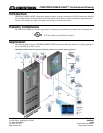
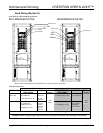
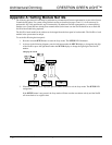
Feed Wiring (Section A)
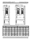
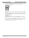
Feed Wiring for MLO and MCB Applications
MCB BREAKER DETAIL
MLO BREAKER DETAIL
"A"
PHASE
"B"
PHASE
"C"
PHASE
NEUTRAL LUG
NEUTRAL BUS
NEUTRAL BUS
"A"
PHASE
"B"
PHASE
"C"
PHASE
NEUTRAL LUG
GROUND LUG
GROUND BARS
GROUND LUG
GROUND BARS
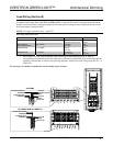
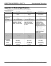
Refer to the following table for information on wiring the feed to the panel.
Feed Wire Information
120 Volt Models
277 Volt Models
TERMINAL CONNECTOR MAX
WIRE RANGE
TORQUE Max
Current
CONNECTOR MAX
WIRE RANGE
TORQUE Max
Current
Neutral and
Main Lugs
10-2/0 AWG (CU) or
6-2/0 AWG (AL)
6 - 300 kcmil (CU or AL)
15 lb-ft
(20.3 Nm)
21 lb-ft
(28.5 Nm)
6-350 kcmil (CU or AL)
1/0-750 kcmil (CU or AL)
275-300 lb-in
(31.1-33.9 Nm)
Neutral Bus 14-10 AWG(CU) or
12-10 AWG (AL)
8 AWG (CU or AL)
6-4 AWG (CU or AL)
20 lb-in
(2.3 Nm)
25 lb-in
(2.8 Nm)
35 lb-in
(4.0 Nm)
225
Amps
14-6 AWG (CU or AL)
14-2/0 AWG (CU or AL)
24-35 lb-in
(2.7-4.0 Nm)
40-50 lb-in
(4.5-5.6 Nm)
250
Amps
Use copper or aluminum conductors only – rated 75°C.
WARNING: Failure to properly tighten lugs may result in poor electrical connection and overheating of the terminals.
6 • CRESTRON GREEN LIGHT Architectural Dimming Installation Guide – DOC. 6688A