11
UVLC Series
Fireplace Screen
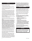
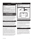
The fireplace screen must be in place when the appli-
ance is operating, and unless other provisions for com-
bustion air are made, the screen must have openings
for the introduction of combustion air.
LG116
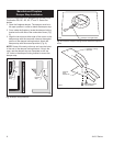
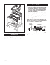
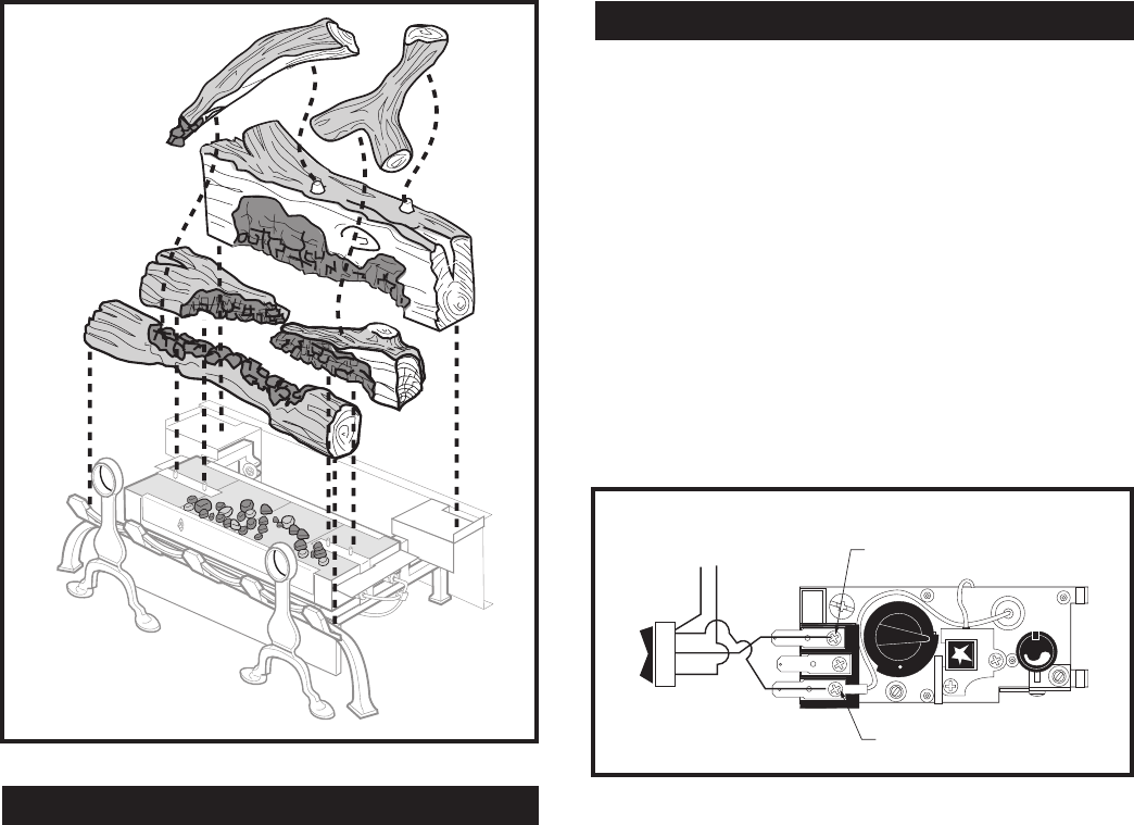
UVLC24 log placement
11/99
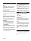
Fig. 8 Placing the logs on the grate assembly.
LG116
PILOT
ON
OFF
PILOT
ADJ
TH
TPTH
TP
L
O
H
I
1
2
3
HV110
Honeywell valve
w/GWSK wall switch
11/99
TP/TH Terminal
TH Terminal
To Optional
GWSK Wall
Switch
HV110
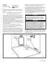
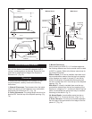
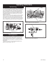
Fig. 9 Connecting a wall switch to the valve termnals.
Remote Wall Switch
(Optional Model GWSK)
1. Thread wire through the electrical knockout located
on either side of the fireplace. Do not cut the wire
or insulation on metal edges. Ensure that the wire
is protected. Run the other end to a conveniently
located wall receptacle box.
2. Attach the wire to the switch and install the switch
into the receptacle box. Attach the cover plate to the
switch.
3. Connect the remaining ends of the optional switch
to the valve at Terminal 3 and the tab connector on
Terminal 1. (Fig. 9)
NOTE: If any of the original wire as supplied with the
appliance must be replaced, it must be replaced with a
wire of at least a 60°C temperature rating.


