


5
W415-0385 / A / 10.02.03
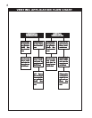
Use only Wolf Steel or Simpson Dura-Vent Model DV-GS
venting components. Minimum and maximum vent lengths,
for both horizontal and vertical installations, and air termi-
nal locations for either system are set out in this manual
and must be adhered to. For Simpson Dura-Vent, follow
the installation procedure provided with the venting com-
ponents.
When using Wolf Steel venting components, use only ap-
proved Wolf Steel rigid / flexible components with the fol-
lowing termination kits: WALL TERMINAL KIT GD422, or
1/12 TO 7/12 PITCH ROOF TERMINAL KIT GD410, 8/12 TO
12/12 ROOF TERMINAL KIT GD411, FLAT ROOF TERMI-
NAL KIT GD412 or PERISCOPE KIT GD401 (for wall pen-
etration below grade). With flexible venting, in conjunction
with the various terminations, use either the 5 foot vent kit
GD420 or the 10 foot vent kit GD430.
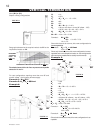
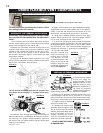
It is recommended to attach the Wolf Steel 45º rigid adap-
tor directly to the unit when terminating horizontally off
the back of the unit. This must be done before attaching
the desired vent system. Once this transition has been
made, venting systems must not be combined.
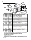
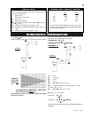
These vent kits allow for either horizontal or vertical venting
of the fireplace. FIGURES 3 & 5. The maximum allowable
horizontal run is 20 feet. The maximum allowable vertical
vent length is 40 feet. The maximum number of 5" vent
connections is two horizontally or three vertically (exclud-
ing the fireplace and the air terminal connections) when
using aluminum flexible venting.
For optimum flame appearance and fireplace perform-
ance, keep the vent length and number of elbows to a
minimum.
The air terminal must remain unobstructed at all times.
Examine the air terminal at least once a year to verify
that it is unobstructed and undamaged.
Purge all gas lines with the glass door of the fireplace
removed. Assure that a continuous gas flow is at the
burner before re-installing the door.
Under extreme vent configurations, allow several minutes
(5-15) for the flame to stabilize after ignition.
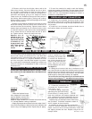
Eight (8") inches is the minimum bend radius allowed
for the 8" diameter flexible liner.
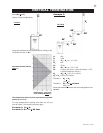
For optimum performance it is recommended that all
horizontal runs have a 1 inch rise per foot when using
Continental flexible vent components.
A terminal shall not terminate directly above a sidewalk
or paved driveway which is located between two sin-
gle family dwellings and serves both dwellings. Local
codes or regulations may require different clearances.
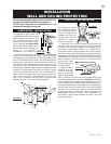
Do not allow the inside liner to bunch up on horizontal or
vertical runs and elbows. Keep it pulled tight. A 1¼" air
gap all around between the inner liner and outer liner is
required for safe operation. Use a firestop when pen-
etrating interior walls, floor or ceiling.
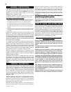
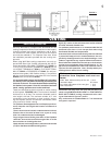
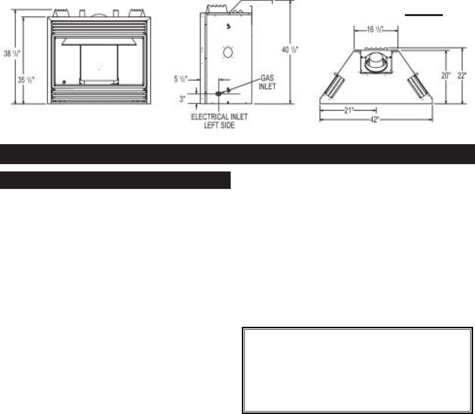
FIGURE 1
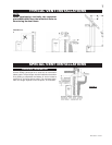
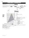
Horizontal runs may have a 0 inch rise per foot in all
cases using SIMPSON DURA-VENT or CONTINENTAL
RIGID OR FLEXIBLE venting components when vent-
ing as illustrated in Figures 3, and 4.
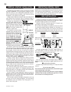
Only a clearance to combustibles of 1" all around the
vent pipe is required.
Minimum clearance to combustible con-
struction from fireplace and vent sur-
faces:
sides, back, bottom and top of the unit 0 inch
recessed depth 22 inches
top, sides and bottom of the vent pipe 1 inch
vent heat shield 1 inch
VENTING
VENTING LENGTHS