


22
W415-0385 / A / 10.02.03
ELECTRICAL INSTALLATION TO BE DONE BY A QUALI-
FIED INSTALLER and must be connected and grounded
in accordance with local codes. In the absence of local
codes, use the current CSA C22.1 C
ANADIAN ELECTRICAL CODE in
Canada or the ANSI/NFPA 70
NATIONAL ELECTRICAL CODE in the
United States.
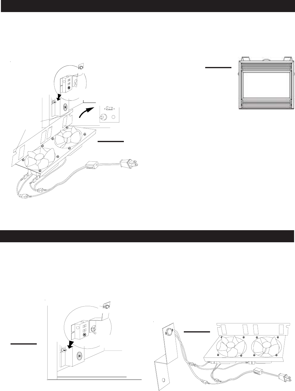
To safely install the fan, turn off the electricity first.
Use of the fan increases the output of heat.
Unplug the power cord from the receptacle. Connect all
wires as shown.
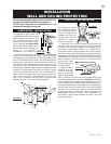
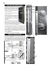
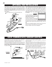
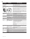
Attach and secure the sensor assembly bracket to the se-
curing stud located next to the receptacle/junction box at
the bottom left of the unit using the lock washer and wing
nut. Ensure that the thermodisc touches the firebox wall.
Plug the power cord back into the receptacle.
When installed, ensure that any excess wire is contained,
preventing it from making contact with moving or hot ob-
jects.
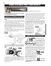
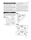
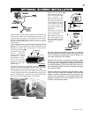
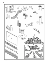
This optional kit is meant to be used only in conjunction
with the GD65 Fan Kit, shown above, which may be or-
dered from your Wolf Steel / Continental dealer.
With the thermostatic sensor option, the fan, when turned
on, becomes thermally activated, and will automatically run
approximately 15-30 minutes after the fireplace has been
lit and for approximately 30-45 minutes after the fireplace
has been turned off.
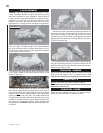
If the fireplace was not previously equipped with a fan:
route a grounded 2-wire, 60hz power cable to the junction
box. At this point, it must be strain relieved and insulated.
The wire harness provided in this kit is a universal har-
ness. When installed, ensure that any excess wire is con-
tained, preventing it from making contact with moving or
hot objects.
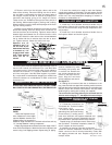
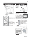
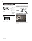
To ease installation of the fan, re-
move the hinge screen and valve
control door (lower louvres) from
the base of the fireplace.
Position the vibration reducing pad
into the clip and onto the threaded
stud at the other end, piercing a hole into the pad. The fan
assembly must be able to be positioned entirely onto the
pad.
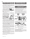
Slide the fan assembly past the controls and into the clip.
Secure using the lock washer and nut provided.
Plug the harness cord into the receptacle.
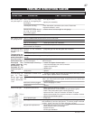
RECEPTACLE /
JUNCTION BOX
OPTIONAL THERMOSTATIC
SENSOR
SLOTS
OPEN ENDED
VARIABLE SPEED/
BRACKET
PIEZO IGNITOR
JUNCTION BOX
THERMODISC
SENSOR ASSEMBLY
BRACKET
RECEPTACLE /
FIGURE 49
FIGURE 48
FIGURE 50
FIGURE 51
OPTIONAL FAN INSTALLATION
GD36 THERMOSTATIC SENSOR CONTROL