


16
W415-0385 / A / 10.02.03
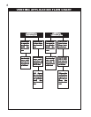
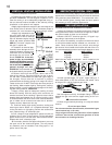
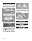
Vertical terminations may display a very active flame. If this
appearance is not desirable, the vent exit must be restricted
using restrictor plate, W080-0454. This reduces the veloc-
ity of the exhaust gases, slowing down the flame pattern
and creating a more traditional appearance.
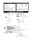
Proceed once the vent installation is complete.
1. Move the fireplace into position and secure using the
nailing tabs and/or secure to the floor through the ¼"diam-
eter holes located at either end of the base.
2. Route a 3/8" N.P.T. black iron gas line, 1/2" type-L cop-
per tubing or equivalent to the fireplace.
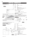
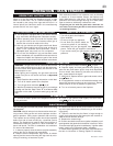
3. For ease of accessibility, an optional remote wall switch
or millivolt thermostat may be installed in a convenient lo-
cation. Route 2-strand (solid core) millivolt wire through
the electrical hole located at the bottom left side of the unit.
The recommended maximum lead length depends on wire
size: WIRE SIZE MAX. LENGTH
14 gauge 100 feet
16 gauge 60 feet
18 gauge 40 feet
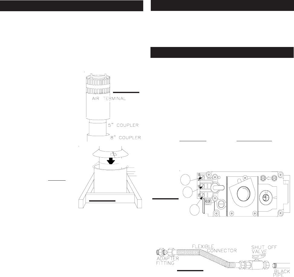
Attach the two leads to terminals 1 and 3 located on the
gas valve.
4. Install rigid black pipe, 1/2" type-L copper tubing or, if
local codes permit, a 3/8" flex connector and shutoff valve
to the gas line and the fireplace gas valve.
Seal and tighten securely. An adapter fitting is required
between the gas valve and the copper tubing or flex con-
nector.
DD
DD
Do not kink flex connector.
5. Check for gas leaks by brushing on a soap and water
solution.
Do not use open flame.
Do not connect either the wall switch, thermostat or gas
valve to electricity (110 volts).
Purge all gas lines with the glass door of the fireplace
removed. Assure that a continuous gas flow is at the
burner before re-installing the door.
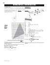
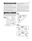
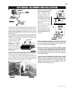
1. Move the fireplace into position.
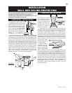
2. Fasten the roof support to the roof using the screws
provided. FIGURE 21. The roof support is optional. In this
case the venting is to be adequately supported using ei-
ther an alternate method suitable to the authority having
jurisdiction or the optional roof support.
3. Apply high temperature sealant to the outer edge of the
inner sleeve of the air terminal. Slip a 5" diameter coupler a
minimum of 2" over the sleeve and secure using 3 screws.
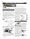
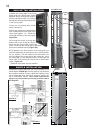
4. Apply high temperature seal-
ant to the outer edge of the of the
outside sleeve of the air terminal.
Slip a 8" diameter coupler over the
sleeve and secure as before. FIG-
URE 25. Trim the 8" coupler even
with the 5" coupler end.
5. Thread the air terminal pipe
assembly down through the roof
support and attach, ensuring that
a minimum 16" of air terminal will
penetrate the roof when fas-
tened. FIGURE 24. If the attic
space is tight, we recommend
threading the Wolf Steel vent pipe
collar or equivalent loosely onto
the air terminal assembly as it is
passed through the attic.
FIGURE 28. The air terminal must
be located vertically and plumb.
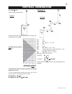
6. Remove nails from the shingles, above and to the
sides of the chimney. Place the flashing over the air termi-
nal and slide it underneath the sides and upper edge of
the shingles. Ensure that the air terminal is properly
centered within the flashing, giving a 3/4" margin all around.
Fasten to the roof. Do NOT nail through the lower portion of
the flashing. Make weather-tight by sealing with caulking.
Where possible, cover the sides and top edges of the flash-
ing with roofing material. FIGURE 23.
7. Apply a heavy bead of waterproof caulking 2 inches
above the flashing. Slide the storm collar around the air
terminal and down to the caulking. Tighten to ensure that a
weather-tight seal between the air terminal and the collar
is achieved. Attach the other storm collar centered between
the air intake and air exhaust slots onto the air terminal.
Tighten securely. Attach the rain cap.
8. Continue adding rigid venting sections, sealing and
securing as above. Attach a 5" collapsed telescopic pipe
to the last section of rigid piping. Secure with screws and
seal. Repeat using a 8" telescopic pipe.
9. Run a bead of high temperature sealant around the
outside of the 5" collar on the fireplace. Pull the adjustable
pipe a minimum of 2" onto the collar. Secure with 3 screws.
Repeat with the 8" telescopic pipe.
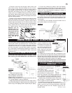
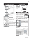
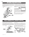
10. In the attic, slide the vent pipe collar down to cover up
the open end of the shield and tighten. This will prevent
any materials, such as insulation, from filling up the 1" air
space around the pipe.
VENT PIPE
SHIELD
VEN
T
PIP
E
COLLA
R
FIGURE 29
FIGURE 28
FIGURE 31
FIGURE 30
P
I
P
I
L
O
T
3
1
2
N
O
L
O
T
H
I
L
O
F
F
O
VERTICAL VENTING INSTALLATION
GAS INSTALLATION
RESTRICTING VERTICAL VENTS