


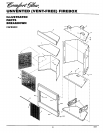

UNVENTED (VENT-FREE) FIREBOX
INSTALLATION
Continued
1. Frame in rough opening. Use dimen-
sions shown in Figure 17 for the rough
opening. If installing in a comer, use
dimensions shown in Figure 18 for the
rough opening. The height is 33"
(CGFB32C) or 34 1/4"(CGFB32NC),
which is the same as the wall opening
in Figure 17.
2. Install gas piping to firebox location.
This installation includes an approved
flexible gas line (if allowed by local
codes) after the manual shutoff valve.
The flexible gas line must be the last item
installed on thegas piping. See Connect-
ing to Gas Supply in log set owner's
manual.
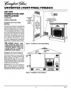
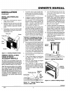
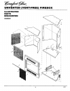
Figure 16- Inserting FireboxInto Cabinet
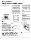
Mantel
III 33" (CGFB32C) I
_ 34 1/4"(_FB32_
•.------ 34 3/4"_
BUILT-IN FIREBOX
INSTALLATION
Built-in installation of this firebox involves
installing firebox into a framed-in enclosure.
This makes the front of firebox flush with
wall. Optional brass trim (GA7090) is avail-
able (see Accessories, page 11) This brass
trim will extend past sides of firebox ap-
proximately 1/2inch. This will cover rough
edges of the wall opening. If installing a
mantel above the firebox, but you must fol-
low the clearances shown in Figure 7, page 7.
Follow the instructions below to install the
fvebox in this manner.
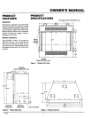
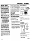
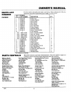
Figure 17- Rough Openingfor Installing
In Waft
718"
Figure 18- Rough Opening for Installing
In Corner
Height Front Width Depth
Model # Actual Framing Actual Framing Actual Framing
CGFB32C 323/s" 33" 34s/16" 343/4.. 1611/16" 173/4"
CGFB32NC 3311hs" 34V4" 34s/18" 34314" 1611h8" 178/4"
3.
4.
5,
6.
7.
8.
9.
Carefully set firebox in front of rough
opening with back of firebox inside wall
opening. IMPORTAIVT: If installing
Brass Trim Kit GA7090, see instructions
included with brass trim accessory. You
must install shoulder screws now.
If using GA3750 blower accessory
(Model CGFB32C only), see Installing
Built-In Installation of Blower Acces-
sory, page 8.
Attach flexible gas line to log set. See
Connecting to Gas Supply in log set
owner's manual.
Carefully insert firebox into rough
opening.
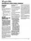
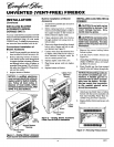
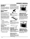
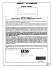
Attach firebox to wall studs using nails
or wood screws through holes in nail-
ing flange (see Figure 19).
Check all gas connections for leaks. See
Checking Gas Connections in log set
owner's manual.
If using optional GA7090 brass trim kit,
install the trim after final finishing and/
or painting of wall. See iusttuctions in-
cluded with brass trim accessory for at-
taching brass trim.
Nails or
Wood
Screws
I
I
'1
NailingFlanges _
Figure 19 - Attaching Firebox to Well
Studs
10 103s73