


OWNER'S MANUAL
INSTALLATION
Continued
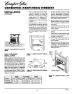
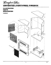
INSTALLING FIREPLACE
SCREEN
1. Insert each rod through nine rings lo-
cated at top of screen.
2. Insert first rod into rear hole in left side
of firebox. Fasten rod to rear hole near
center of firebox using black shoulder
screw.
3. Insert other rod into front hole on right
side of firebox and fasten using remain-
ing shoulder screw.
Rear Hole
Screw
Figure 12- Installing Fireplace Screen
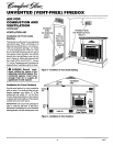
FIREBOX INSTALLATION
USING OPTIONAL
ACCESSORY MANTELS
1. Assemble cabinet mantel, hearth base,
and perimeter trim (Included with man-
tel). Assembly instructions are included
with each accessory,
2. If using an optional GA3750 blower
(CGFB32C model only), install a prop-
erly grounded, 120 volt three-prong
electrical outlet at firebox location if an
outlet is not there. If possible, locate
outlet so cabinet mantel will cover it
when installed (see Figure 14).
3. Install gas piping tofirebox location. This
installation includes an approved flex-
ible gas line (if allowed by local codes)
and a manual shutoff valve. The flexible
gas line must be the last item installed
on the gas piping. See Connecting to Gas
Supply in your log set owner's manual.
4+
5+
6.
This firebox may be installed using the cabi- 7.
net mantel andhearthbase accessories against
a wall in your home. Follow the instructions 8.
below m install the firebox in this manner.
Note:Theinstructions below show installa-
tion using GMCIlF/GMCI2U/GMC13F
series cabinet mantels and the GC3333F/
"GC3334U/GC3335F series hearth base ac-
cessories. The hearth base accessory shown
is optional for this installation. You can
install firebox and cabinet mantel directly
on the floor.
NOTICE: A qualified service per-
son must connect firebox to gas
supply. Follow all local codes.
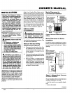
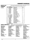
Place hearth base accessory against wall
at installation location. Cut an access
hole in hearth top to run flexible gas line
to firebox (see Figure 13). Make sure to
locate access hole so cabinet mantel will
cover it when installed. Note: You can
secure base to floor using wood screws.
Countersink screw heads and putty over.
Route flexibie gas line through access
hole in hearth base.
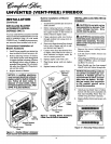
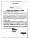
Center cabinet mantel on hearth base
(see Figure 14). Make sure mantel is
flush against wall.
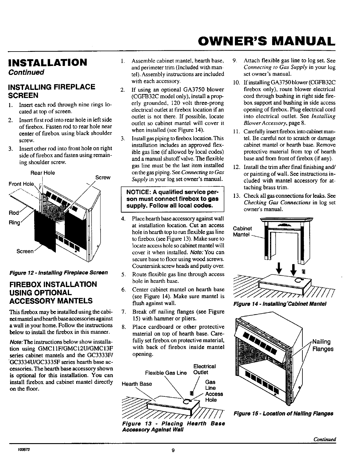
Break off nailing flanges (see Figure
15) with hammer or pliers.
Place cardboard or other protective
material on top of hearth base. Care-
fully set firebox on protective material,
with back of firebox inside mantei
opening.
Electrical
FlexibleGas Line Outlet
HearthBase _ / Gas
_ .j/ Line
Access
Figure 13 - Placing Hearth Base
Accessory Against Wall
9.
10.
Attach flexible gas line to log set. See
Connecting to Gas Supply in your log
set owner's manual.
If installing GA3750 blower (CGFB32C
firebox only), route blower electrical
cord through bushing in right side fire-
box support and bushing in side access
opening of firebox. Plug electrical cord
into electrical outlet. See Installing
Blower Accessory, page 8.
11. Carefully insert firebox into eabinet man-
tel. Be careful not to scratch or damage
cabinet mantel or hearth base. Remove
protective material from top of hearth
base and from front of firebox (if any).
12. Install the trim after final finishing and/
or painting of wall. See instructions in-
cluded with mantel accessory for at-
taching brass trim.
13. Check all gas connections for leaks. See
Checking Gas Connections in log set
owner's manual.
Cabinet
Figure 14 - Installing'Cabinet Mantel
,Nailing
Figure 15- Location of Nailing Flanges
Continued
f03573 9