


107434-01C
For more information, visit www.desatech.com
For more information, visit www.desatech.com
9
9
INSTALLATION
Continued
Test Pressures Equal To or Less Than 1/2 PSIG (3.5 kPa)
1. Close equipment shutoff valve (see Figure 7).
2. Pressurize supply piping system by either using compressed
air or opening main gas valve located on or near gas meter.
3. Check all joints from gas meter to equipment shutoff valve (see
Figure 8). Apply a noncorrosive leak detection fluid to gas joints.
Bubbles forming show a leak.
4. Correct all leaks at once.
Pressure Testing Heater Gas Connections
1. Open equipment shutoff valve (see Figure 7).
2. Open main gas valve located on or near gas meter.
3. Make sure control knob of heater is in the OFF position.
4. Check all joints from equipment shutoff valve to control valve
(see Figure 8). Apply a noncorrosive leak detection fluid to
gas joints. Bubbles forming show a leak.
5. Correct all leaks at once.
6. Light heater (see Operating Heater, pages 13 and 14). Check
all other internal joints for leaks.
7. Turn off heater (see To Turn Off Gas to Appliance, page 14).
ON
POSIT
O
PO
S
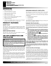
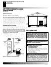
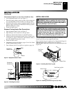
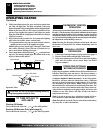
Figure 7- Equipment Shutoff Valve
Closed
Equipment
Shutoff Valve
Open
WARNING: Failure to position the parts in accor-
dance with these diagrams or failure to use only parts
specifically approved with this heater may result in
property damage or personal injury.
INSTALLING LOGS
It is very important to install the logs exactly as instructed. Do not
modify logs. Only use logs supplied with heater.
Place one-piece log set on grate to fit as illustrated in Figure 10.
Make sure log sits flat on firebox floor (see Figure 9).
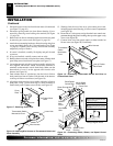
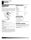
IMPORTANT:
Make sure log does not cover any burner ports (see
Figure 10).
CAUTION: After installation and periodically there-
after, check to ensure that no flame comes in contact
with any log. With the heater set to High, check to see
if flames contact any log. If so, reposition logs ac-
cording to the log installation instructions in this
manual. Flames contacting logs will create soot.
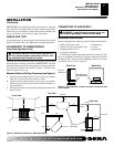
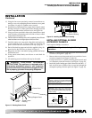
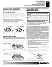
Figure 8 - Checking Gas Joints
Control Valve Location
Gas Meter
Equipment
Shutoff Valve
O
F
F
P
I
L
O
T
O
N
H
I
L
O
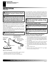
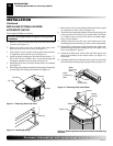
Figure 9 - Installing One-Piece Log Set
One Piece
Log Set
Firebox Floor
Figure 10 - Installing One-Piece Log set (Top View)
One Piece Log Set
Burner Ports
INSTALLATION
Checking Gas Connections (Cont.)
Installing Logs