


107434-01C
For more information, visit www.desatech.com
For more information, visit www.desatech.com
11
11
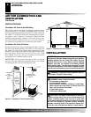
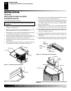
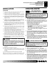
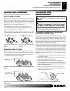
13. Using the four screws previously removed, mount blower as-
sembly to stove by reattaching blower brackets to rear panel
(see Figure 14, page 10). Tighten screws securely.
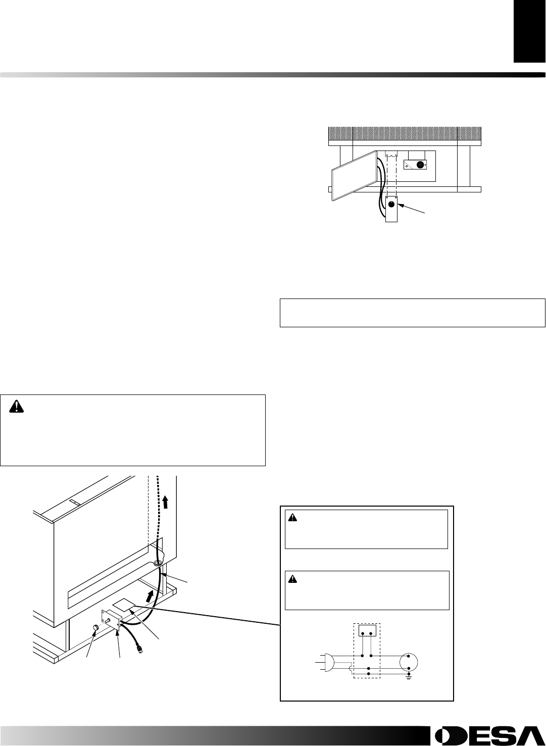
14. Install plastic control knob onto output shaft of speed control
housing (see Figure 15). Place speed control housing just inside
control compartment door in front of stove (see Figure 16).
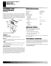
15. Using two screws provided in blower kit, mount blower speed
control housing to mounting tab in left side of lower control
compartment (see Figure 16).
16. Check to make sure that the power cord is completely clear of blower
wheel and there are no foreign objects in blower wheel.
17. Carefully replace stove top panel. Align holes and replace six
screws removed in step 1, page 10. Slide top trim onto top
panel. Attach with two screws removed in step 1, page 10.
18. Peel off the backing paper and stick the supplied wiring dia-
gram decal on the stove floor as shown in Figure 15.
19. Plug power cord into a convenient 3-prong grounded wall recep-
tacle near the stove.
20. Using speed control knob, turn blower on and check for
operation.
21. All remaining parts from blower kit may be discarded.
Power Cord
Speed Control
Housing
Control
Knob
Figure 15 - Routing Power Cord
Wiring Diagram Decal
INSTALLATION
Continued
Figure 16 - Installing Blower Control Housing
Blower Speed
Control Housing
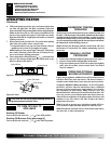
WARNING: ELECTRICAL GROUNDING
INSTRUCTIONS This appliance is equipped with a
three-prong (grounding) plug for your protection
against shock hazard and should be plugged directly
into a properly grounded three-prong receptacle.
101584-05
120 Vac. 60 Hz. . 78 Amps
DESA International, Bowling Green, KY
WARNING: Never attempt to service heater while it
is plugged in, operating, or hot. Burns and electrical
shock could result. Only a qualified service person
should service or repair heater.
If any of the original wire as supplied with the appliance must be
replaced, it must be replaced with 105°C wire or it’s equivalent.
WARNING: Label all wires prior to disconnection
when servicing controls. Wiring errors can cause im-
proper and dangerous operation. Verify proper opera-
tion after servicing.
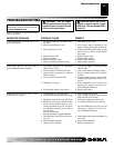
Variable
Fan Switch
WhiteWhite
Black
Green
On
110/115
V.A.C.
Blower
Motor
Black
Black
Black
Off
INSTALLING OPTIONAL BLOWER
ACCESSORY GA3650TA
Tools required: Phillips screwdriver
NOTICE: Shut off gas heater during the following blower
installation.
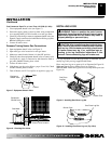
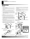
1. Remove 2 screws from rear tabs on top trim. Pull trim forward
to remove (see Figure 11, page 10).
2. Remove three screws from under top lip on each side of stove
to remove top panel (see Figure 11, page 10).
3. Facing front of stove, carefully slide top panel forward until
it is completely removed from stove (see Figure 11, page 10).
4. Install one plastic bushing provided in blower kit into the 1
1
/2"
hole in the left rear of firebox floor. Access hole through the
rectangular opening in the rear panel (see Figure 12, page 10).
INSTALLATION
Installing Optional Blower Accessory GA3750 (Cont.)
Installing Optional Blower Accessory GA3650TA