


107434-01C
For more information, visit www.desatech.com
For more information, visit www.desatech.com
15
15
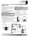
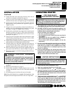
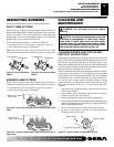
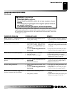
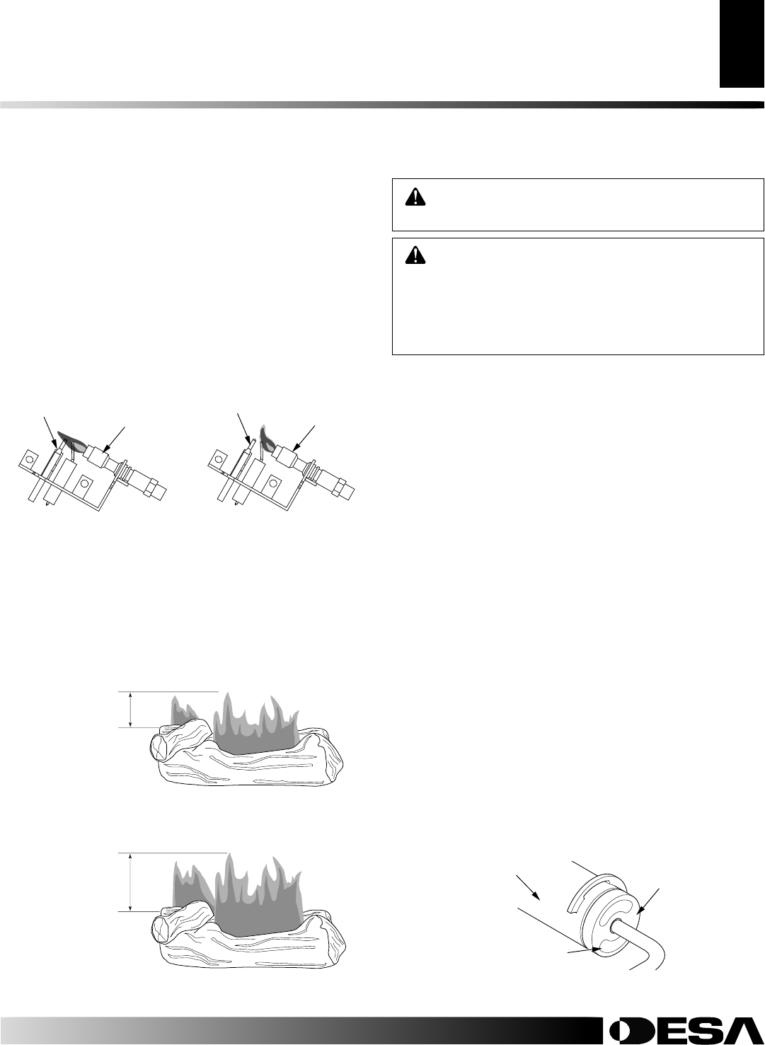
BURNER FLAME PATTERN
Figure 25 shows a correct burner flame pattern. Figure 26 shows an
incorrect burner flame pattern. If burner flame pattern is incorrect,
• turn heater off (see To Turn Off Gas to Appliance, page 14)
• see Troubleshooting, pages 17 through 19
Figure 25 - Correct Flame Pattern with Control Knob Set to High
Flame
Figure 26 - Incorrect Flame Pattern with Control Knob Set to
High Flame
Approx. 3-6" Above
Top of Logs
More Than 8"
Above Top of Logs
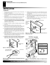
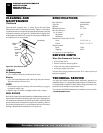
INSPECTING BURNERS
Check pilot flame pattern and burner flame patterns often.
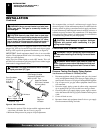
PILOT FLAME PATTERN
Figure 23 shows a correct pilot flame pattern. Figure 24 shows an
incorrect pilot flame pattern. (
Note:
Appearance of pilot assembly
may vary by model). The incorrect pilot flame is not touching the
thermocouple. This will cause the thermocouple to cool. When the
thermocouple cools, the heater will shut down.
If pilot flame pattern is incorrect, as shown in Figure 24
• turn heater off (see To Turn Off Gas to Appliance, page 14)
• see Troubleshooting, pages 17 through 19
Note:
The pilot flame on the natural gas units will have a slight
curve but flame should be blue and have no yellow or orange color.
Figure 23 - Correct Pilot Flame
Pattern
Figure 24 - Incorrect Pilot Flame
Pattern
Thermocouple
Pilot Burner
Pilot Burner
Thermocouple
CLEANING AND
MAINTENANCE
WARNING: Turn off heater and let cool before
cleaning.
CAUTION: You must keep control areas, burner, and
circulating air passageways of heater clean. Inspect
these areas of heater before each use. Have heater
inspected yearly by a qualified service person. Heater
may need more frequent cleaning due to excessive lint
from carpeting, bedding material, pet hair, etc.
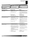
CLEANING BURNER INJECTOR HOLDER
AND PILOT AIR INLET HOLE
The primary air inlet holes allow the proper amount of air to mix with
the gas. This provides a clean burning flame. Keep these holes clear of
dust, dirt,lint, and pet hair. Clean these air inlet holes prior to each
heating season. Blocked air holes will create soot. We recommend that
you clean the unit every three months during operation and have heater
inspected yearly by a qualified service person.
We also recommend that you keep the burner tube and pilot assembly
clean and free of dust and dirt. To clean these parts we recommend
using compressed air no greater than 30 PSI. Your local computer
store, hardware store, or home center may carry compressed air in a
can. You can use a vacuum cleaner in the blow position. If using
compressed air in a can, please follow the directions on the can. If you
don't follow directions on the can, you could damage the pilot
assembly.
1. Shut off the unit, including the pilot. Allow the unit to cool for
at least thirty minutes.
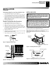
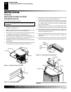
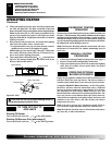
2. Inspect burner, pilot, and primary air inlet holes on injector
holder for dust and dirt (see Figure 27).
3. Blow air through the ports/slots and holes in the burner.
4. Check the injector holder located at the end of the burner tube again.
Remove any large particles of dust, dirt, lint, or pet hair with a soft
cloth or vacuum cleaner nozzle.
5. Blow air into the primary air holes on the injector holder.
6. In case any large clumps of dust have now been pushed into
the burner repeat steps 3 and 4.
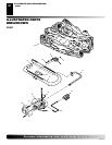
Figure 27 - Injector Holder On Outlet Burner Tube
Burner Tube
Injector Holder
Primary Air Inlet Holes
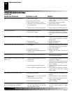
INSPECTING BURNERS
pilot Flame Pattern
Burner Flame Pattern
CLEANING AND MAINTENANCE
Cleaning Burner Injector Holder and Pilot Air Inlet Hole