


107434-01C
For more information, visit www.desatech.com
For more information, visit www.desatech.com
13
13
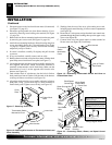
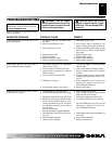
1. STOP! Read the safety information, above.
2. Make sure equipment shutoff valve is fully open.
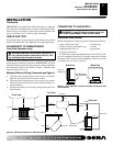
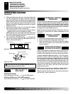
3. Turn control knob clockwise
Clockwise
to the OFF position.
4. Wait five (5) minutes to clear out any gas. Then smell for
gas, including near the floor. If you smell gas, STOP! Fol-
low “B” in the safety information, above. If you don’t smell
gas, go to the next step.
5. Turn control knob counterclockwise
C-clockwise
to the PILOT
position. Press in control knob for five (5) seconds (see Fig-
ure 21, page 14).
Note:
You may be running this heater for
the first time after hooking up to gas supply. If so, the con-
trol knob may need to be pressed in for 30 seconds or more.
This will allow air to bleed from the gas system.
LIGHTING INSTRUCTIONS
NOTICE: During initial operation of new heater, burning
logs will give off a paper-burning smell. Orange flame
will also be present. Open a window to vent smell. This
will only last a few hours.
OPERATING HEATER
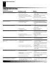
FOR YOUR SAFETY
READ BEFORE LIGHTING
WARNING: If you do not follow these instructions
exactly, a fire or explosion may result causing prop-
erty damage, personal injury or loss of life.
A. This appliance has a pilot which must be lighted by hand.
When lighting the pilot, follow these instructions exactly.
B. BEFORE LIGHTING smell all around the appliance area
for gas. Be sure to smell next to the floor because some gas
is heavier than air and will settle on the floor.
WHAT TO DO IF YOU SMELL GAS
• Do not try to light any appliance.
• Do not touch any electric switch; do not use any phone in
your building.
• Immediately call your gas supplier from a neighbor’s
phone. Follow the gas supplier’s instructions.
• If you cannot reach your gas supplier, call the fire
department.
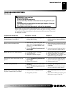
C. Use only your hand to push in or turn the gas control knob.
Never use tools. If the knob will not push in or turn by
hand, don’t try to repair it, call a qualified service techni-
cian or gas supplier. Force or attempted repair may result
in a fire or explosion.
D. Do not use this appliance if any part has been under water.
Immediately call a qualified service technician to inspect the
appliance and to replace any part of the control system and
any gas control which has been under water.
WARNING: ELECTRICAL GROUNDING
INSTRUCTIONS
This appliance is equipped with a three-prong (ground-
ing) plug for your protection against shock hazard
and should be plugged directly into a properly
grounded three-prong receptacle.
INSTALLATION
Continued
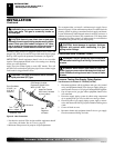
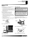
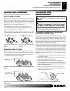
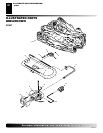
18. Connect the black wire from speed control to blue wire on
switch/cover assembly (see Figure 20, page 12).
19. Connect red wire from switch/cover assembly to remaining
terminal on blower motor (see Figure 20, page 12). Push firmly.
20. Attach green wire from speed control to front tab of blower
housing using screw provided (see Figure 20, page 12).
Tighten securely.
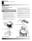
21. Using the four screws previously removed, mount blower as-
sembly to stove by reattaching blower brackets to rear panel
(see Figure 14, page 10). Tighten screws securely.
22. Install plastic control knob onto output shaft of speed control
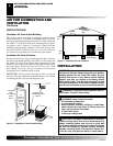
housing (see Figure 20, page 12). Place speed control hous-
ing just inside control compartment door in front of stove
(see Figure 16, page 11).
23. Using two screws provided in blower kit, mount blower speed
control housing to mounting tab in left side of lower control
compartment (see Figure 16, page 11).
24. Check to make sure that the power cord is completely clear of blower
wheel and there are no foreign objects in blower wheel.
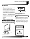
25. Carefully replace stove top panel. Align holes and replace six
screws removed in step 1, page 11. Slide top trim over sides of
top panel. Attach with 2 screws removed in step 1, page 11.
26. Peel off the backing paper and stick the supplied wiring dia-
gram decal on the stove floor as shown in Figure 20, page 12.
27. Plug power cord into a convenient 3-prong grounded wall recep-
tacle near the stove.
28. Using speed control knob, turn blower on and check for
operation.
29. Install logs (see Installing Logs, page 9).
30. Install screen assembly by aligning keyhole slots in screen
assembly and shoulder screws on stove. Push back and down
to secure.
31. All remaining parts from blower kit may be discarded.
Note:
If any of the origianl wire, as supplied with the appliance, must
be replaced, it must be replaced with 105°C wire or it’s equivalent.
INSTALLATION
Installing Optional Blower Accessory GA3650YA (Cont.)
OPERATING HEATER
For Your Safety Read Before Lighting
Lighting Instructions