


107434-01C
For more information, visit www.desatech.com
For more information, visit www.desatech.com
12
INSTALLATION
Continued
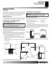
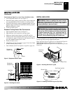
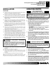
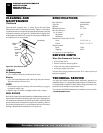
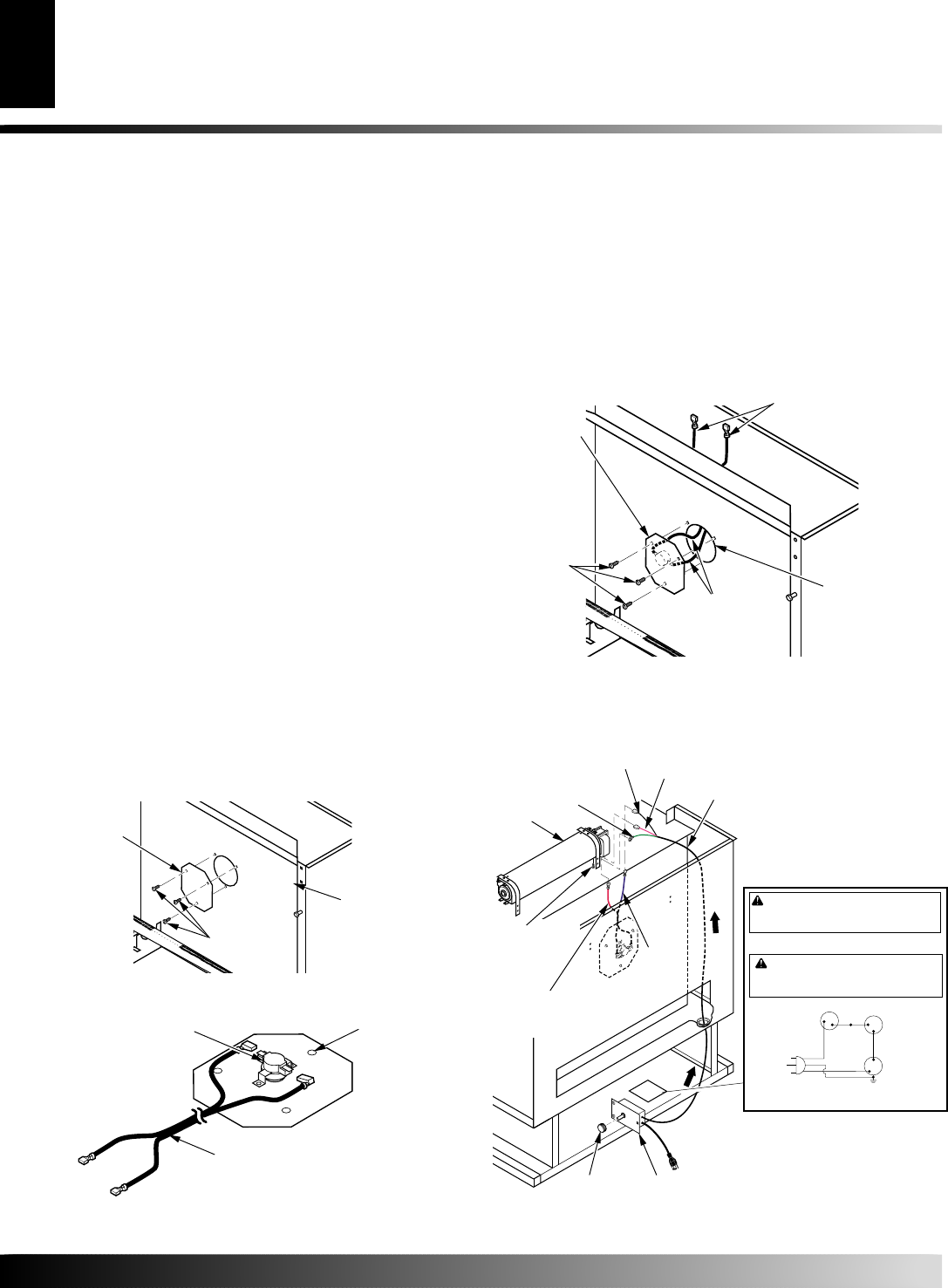
Figure 18 - Attaching Wire Harness to Thermostatic Switch and
Cover Assembly
Thermostatic Switch
Mounted to Cover
Wire Harness
Lower Hole
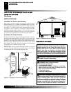
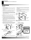
Figure 17 - Removing Cover Plate
Cover
Plate
Firebox Back
Panel
Screws
5. Disconnect power cord wires from blower motor (if connected)
(see Figure 13, page 10).
6. Disconnect green ground wire from blower housing (if con-
nected) by removing screw holding wire terminal (see Figure
13, page 10).
7. Remove the two blower mounting brackets from the rear panel
by removing two screws each (see Figure 14, page 10).
8. Attach the two mounting brackets to blower housing using four
screws provided in blower kit (2 for each bracket) (see Figure
14, page 10). Tighten screws securely. Place blower assembly
temporarily on top of firebox.
9. If screen is installed, carefully lift slightly and pull forward
to remove.
10. If logs are installed, carefully remove and set aside.
11. Remove three screws and cover plate from center of firebox back
panel. Keep screws but discard cover plate (see Figure 17).
12. Locate thermostatic switch/cover plate assembly and wire har-
ness supplied with blower. Attach wire harness terminals to
terminals on thermostatic switch. Push firmly. Make sure the
bottom hole of cover is on the opposite side from the wire
harness (see Figure 18).
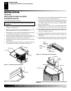
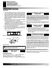
13. Feed terminal ends of wire harness into the hole in firebox
back panel from front of firebox. Pull the ends of the harness
to the top of firebox near blower (see Figure 19).
14. Align holes in the switch/cover assembly with holes in firebox
back panel. Using 3 screws from step 11, attach assembly to
firebox back panel. Tighten screws firmly (see Figure 19).
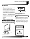
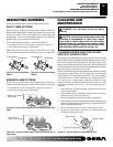
15. Working from the rear of the stove, place entire power cord,
including speed control housing, in lower control compartment
(see Figure 20).
16. Route ends of 3-wire power cord up from the lower control com-
partment through the plastic bushing, then up to the upper cavity
of stove (see Figure 20).
17. Connect white wire from speed control to either terminal on
blower motor (see Figure 20). Push firmly.
Figure 19 - Assembling Thermostatic Switch and Cover to
Firebox Back Panel
Thermostatic
Switch
Mounted to
Cover
Wire
Harness
Hole in Firebox
Back Panel
Screws
Wire Harness
Power Cord
Speed Control
Housing
Control
Knob
Wiring Diagram Decal
Blower
Red Switch
Wire
Green Ground Wire
Ground
Wire
Screw
White Speed
Control Wire
Black Speed
Control Wire
Blue
Switch
Wire
Figure 20 - Connecting Switch, Blower, and Speed Control
Wires
Red
Variable
Fan Switch
Fan Switch
(N.O.)
Green
White
On
110/115
V.A.C.
Blower
Motor
Black
Off
1
2
Black
Blue
120 Vac. 60 Hz. 90 Amps
DESA International, Bowling Green, KY
WARNING: Never attempt to service heater while it
is plugged in, operating, or hot. Burns and electrical
shock could result. Only a qualified service person
should service or repair heater.
If any of the original wire as supplied with the appliance must be
replaced, it must be replaced with 105°C wire or it’s equivalent.
WARNING: Label all wires prior to disconnection
when servicing controls. Wiring errors can cause im-
proper and dangerous operation. Verify proper operation
after servicing.
INSTALLATION
Installing Optional Blower Accessory GA3650TA (Cont.)