


9
Chateau™
20011956
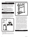
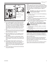
NOTE: If you need to test the inlet pressure and/or
manifold pressure, there are two (2) test ports available
along the right side front edge between the firebox side
and outer casing. The upper test port is inlet pressure.
The lower test port is manifold pressure. (Refer to
Figure 8)
CAUTION: Turn off the gas supply before
removing test port plug.
23. Using a 7/16” nut driver, remove the threaded plug
from the test port.
24. Thread the supplied extension adaptor into the
open test port.
25. Attach a 1/4” diameter pressure gauge flexible hose
fully onto the barb of the adaptor.
26. Turn on gas supply and operate valve with remote
control as needed to indicate gas pressure.
CAUTION: Turn off the fireplace and gas
supply before removing test port adaptor
and replacing plug.
27. After test, remove extension adaptor and replace
plug securely.
28. Turn on gas supply and check that plugs are tight
and leak free.
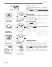
Special Feature for Cold Climates
This gas control system has the option of a continu-
ous pilot feature. This allows the user to change from
a spark to pilot system to a standing pilot system for
direct vent appliances during cold climate conditions to
keep the firebox warm.
When the continuous pilot mode is activated and the
fireplace is turned ON, the pilot will spark and light.
When the fireplace is turned OFF, the pilot will stay ON
when the main burner shuts OFF.
The continuous pilot mode can be activated or de-acti-
vated by the hand held remote control transmitter.
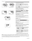
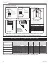
16. If you chose to install the optional back-up battery
pack (No. DVTBBK), you must install a wall box
within 15 feet (4.6 m) of the fireplace. Assemble the
connectors on one end of the supplied extension
wire harness to the mating connectors on wire har-
ness within the control box. Make sure to connect
black coded wire to black and red coded wire to
red.
17. The other end of the extension wire harness should
be connected to the wiring of the back-up battery
holder located within a wall box.
18. Insert the supplied four (4) “AA” batteries into the
battery older. Be sure to note correct polarity for
each battery.
19. Mount electrical wall box containing back-up bat
-
teries at a convenient location with 15 feet (4.6 m)
of the fireplace. Cover wall box using a blank wall
plate.
20. The fireplace remote system is ready for use.
21. Reassemble access panel, burner assembly, gas
supply connector, brick panels, logs, embers,
andirons and lava rock in reverse order of removal.
(Refer to Log, Lava Rock and Ember Placement
section.
22. Turn on gas supply and check that all connections
are tight and leak free.
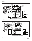
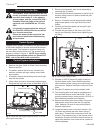
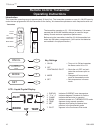
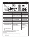
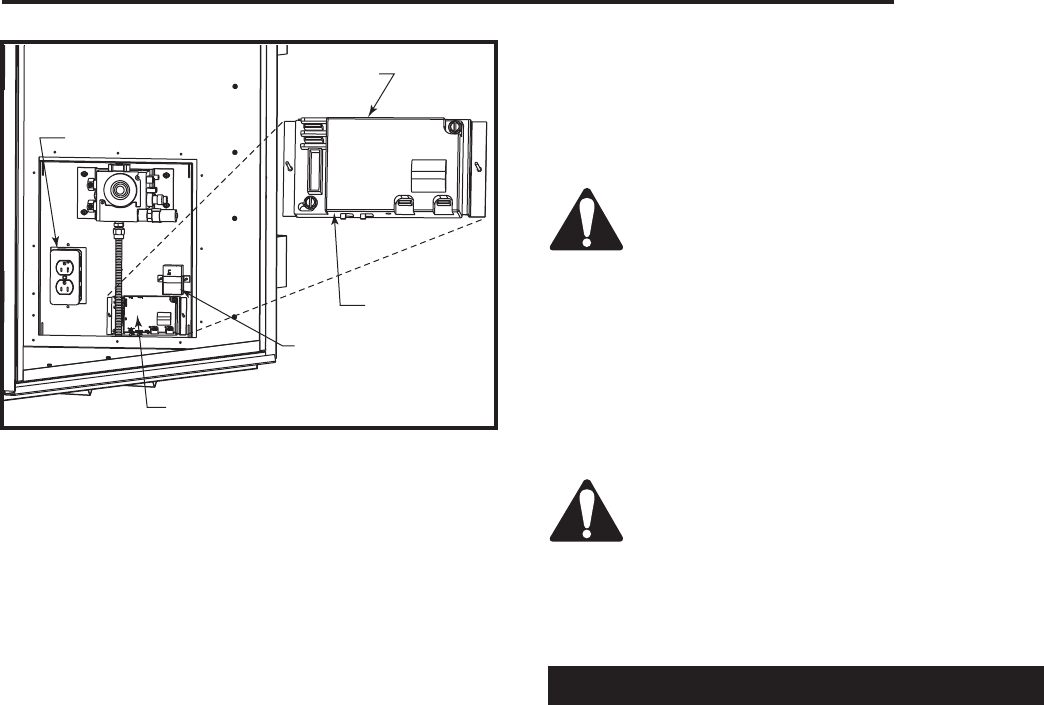
ADJ.
S
Remote/Off
IPI
POWER
AUX
Learn
I
Continous
Pilot
Off/On
Junction Box
Main Module
FP1792
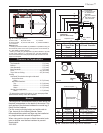
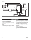
Fig. 10 Connect 120V AC electrical supply.
Main Module
Learn
Button
Power Module