


8
Chateau™
20011956
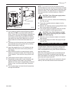
The fireplace, when installed, must be elec-
trically connected and grounded in accord-
ance with local codes or, in the absence
of local codes, with the current CSA C22.1
Canadian Electrical Code or the national
electrical code ANSI/NFPA No. 70 in the
USA.
It is strongly suggested that the wiring of
the Electrical Junction Box be carried out
by a licensed electrician.
Ensure the power to the supply line has
been disconnected before commencing
this procedure.
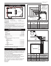
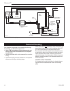
Electrical Junction Box
Control System
The gas control system is located on the right hand side
of the firebox behind an access panel and the decora-
tive brick panel. The fireplace is operated using only
the hand held remote control unit. The system wiring
diagram is shown in Figure 11. NOTE: If you choose
to install the optional battery back-up, (Model DVT-
BBK), refer to Item #16 in the next section.
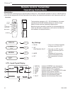
Control System Installation
1. Locate the fireplace in the desired location.
2. Remove the glass. Refer to Glass Frame Assembly
Removal section.
3. If installed, remove the lava rock, volcanic rock,
andirons, embers and logs, making note of each
log’s location.
4. If installed, remove the refractory brick panel right
side and rear pieces.
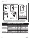
5.
Using a back-up wrench, disconnect the gas supply
fitting near the right rear corner of the firebox. (Fig. 8)
6. Remove pilot assembly from burner assembly by
removing two (2) screws.
7. Carefully slide the burner assembly to the left out of
the way, taking care not to bend or break the pilot
tubes or wiring.
8. Remove 13 screws around the perimeter holding
large access panel on the right hand side of the
firebox.
9. Carefully pull back the panel just enough to gain
access to control box.
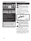
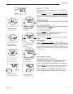
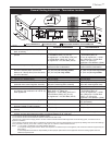
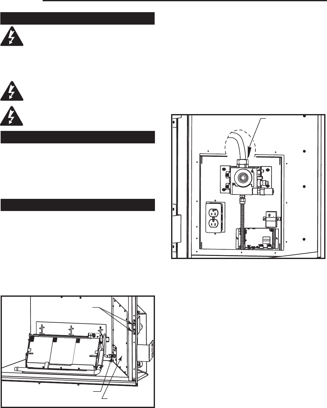
10. Connect the gas supply to the valve. (Fig. 9) Be
sure to use a back-up wrench when tightening sup-
ply fitting.
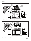
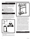
Gas Supply
Fitting
FP1794
Fig. 9 Connect gas supply to valve.
11. Connect a 120V AC electrical supply to the junc-
tion box duplex outlet. Use a Romex-type strain
relief connector when running wires out through the
box knockout. Replace the duplex outlet and cover
plate.
12. Plug the AC adaptor plug into the duplex outlet.
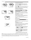
13. This control system must now be programmed to
the hand held remote control transmitter. To pro-
gram the remote control, make sure the 120V AC is
connected and powered to the fireplace.
14. Remove the battery door on the back of the hand
held remote control and install two (2) supplied
“AAA” batteries. Be sure to note correct polarity.
Replace battery door.
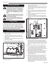
15. Locate the learn button on the main module. (Fig.
10) Press and release the learn button using a
pencil point. There will be a beep sound from the
module. Then press any key on the remote control
transmitter. Once the module’s internal receiver ac-
cepts the transmitter code, there will be a series of
confirming beeps.
Gas Supply Fitting
FP1793
Fig. 8 Disconnect gas supply fitting and remove 13 screws
securing the cover plate.
Cover Plate
Pressure Test Ports