


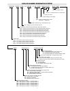

O O O O - O O O - 0 0 H X 0 0 0 W - X 0 0 . 0 0 D - 0 0 0 V 0 0 P - 0 0 0 . 0 kW
000.0kW, (16kW/Ft.
2
MAX.)
Phase: 1P = Single Phase’ 3P = Three Phase
0 = Number of circuits
000V = Heater voltage (up thru 600V)
00.00 = Depth of heater frame in inches
(06.50 min. – 36.00 max.)
000W = Width of duct in inches (08 thru 120)
00H = Height of duct in inches (06 thru 40)
Terminal box construction and terminal box and frame material:
GPA = General purpose terminal box and all aluminized steel construction
GPP = General purpose terminal box and all painted steel construction
GPZ = General purpose terminal box and all plated steel construction
GPS = General purpose terminal box and all stainless steel construction
DPA = Drip proof terminal box and aluminized steel construction
DPP = Drip proof terminal box and painted steel construction
DPZ = Drip proof terminal box and plated steel construction
DPS = Drip proof terminal box and stainless steel construction
General style:
DHRI = Duct heater, remote controls, insert type
DHRF = Duct heater, remote controls, flanged type
DHII = Duct heater, integral controls, insert type
DHIF = Duct heater, integral controls, flanged type
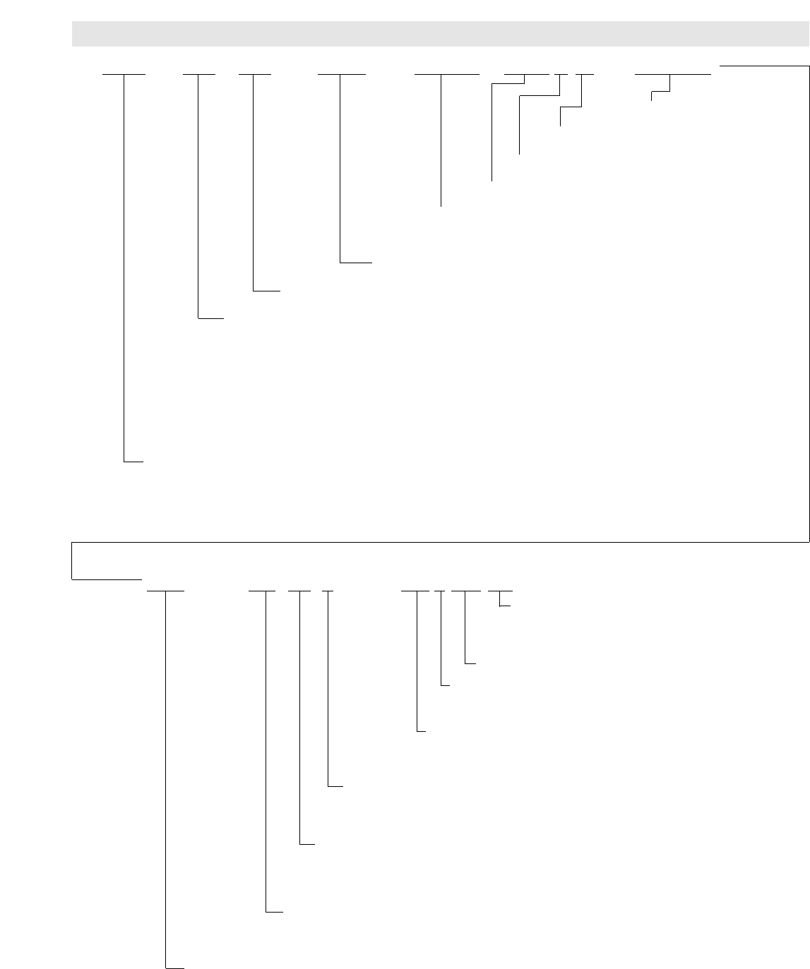
0 M P - O O O O O - O O O 0 0 0 O O
Disconnecting Means:
ND = Nonfused disconnect switch (200A max.)
FD = Fused disconnect switch (48A max.)
TB = Terminal block (200A max.), disconnect switch by others
Control circuit voltage: 000 = 120, 208, 240, or 277V
Control circuit power supply:
T = Control circuit by integral transformer (120V Sec. Only)
R = Remote control circuit by customer (120, 208, 240, or 277V)
Fan interlock method:
AS = Air flow switch
FI = Fan interlock relay
FD = Fan interlock relay with fan delay
Heating element termination:
M = Threaded terminals with mica insulation
R = Threaded terminals with ceramic insulation (480V max.)
H = Hermetic seals (480V max.)
Method of attaching heating element to heater frame:
WA = Painted steel fin and sheath
GW = Mounting washer staked to element sheath with gasket
BF = Brass fitting with gasket
SS = Stainless steel fin and sheath
Sheath, fin, and finish of heating element:
PS = Painted steel fin and sheath
MO = Monel fin and sheath
SS = Stainless steel fin and sheath
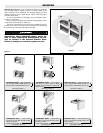
Mounting position of heater:
1MP = See Figure 16 on page 4, mounting position 1
2MP = See Figure 16 on page 4, mounting position 2
3MP = See Figure 16 on page 4, mounting position 3
4MP = See Figure 16 on page 4, mounting position 4
5MP = See Figure 16 on page 4, mounting position 5
6MP = See Figure 16 on page 4, mounting position 6
-7-
CATALOG NUMBER DESIGNATION SYSTEM