


GENERAL
Limitations: Ductwork must be in accordance with one of the fol-
lowing: Standards of the National Fire Protection Association for
the installation of Air Conditioning and Ventilating Systems of
other than Resident Type (Pamphlet 90A) or Residential Type
Warm Air Heating and Air Conditioning Systems (Pamphlet 90B).
Location: Chromalox Duct Heaters may be located anywhere in
the duct system.
NOTE: The minimum distances shown are limitations. Wherever
possible, locate as far away from these limits as practical. In any
case, this distance with any required airflow correction must be
sufficient to accomplish even air flow at a velocity equal to, at
least, the minimum stated on the heater nameplate.
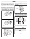
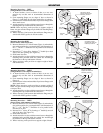
1. Installation near heat pump, central air conditioner, filters or
humidifier. (Refer to Figure 5).
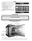
2. Installation near air handler discharge. (Refer to Figure 6).
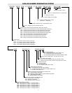
3. Installation in branch duct take-off. (Refer to Figure 7).
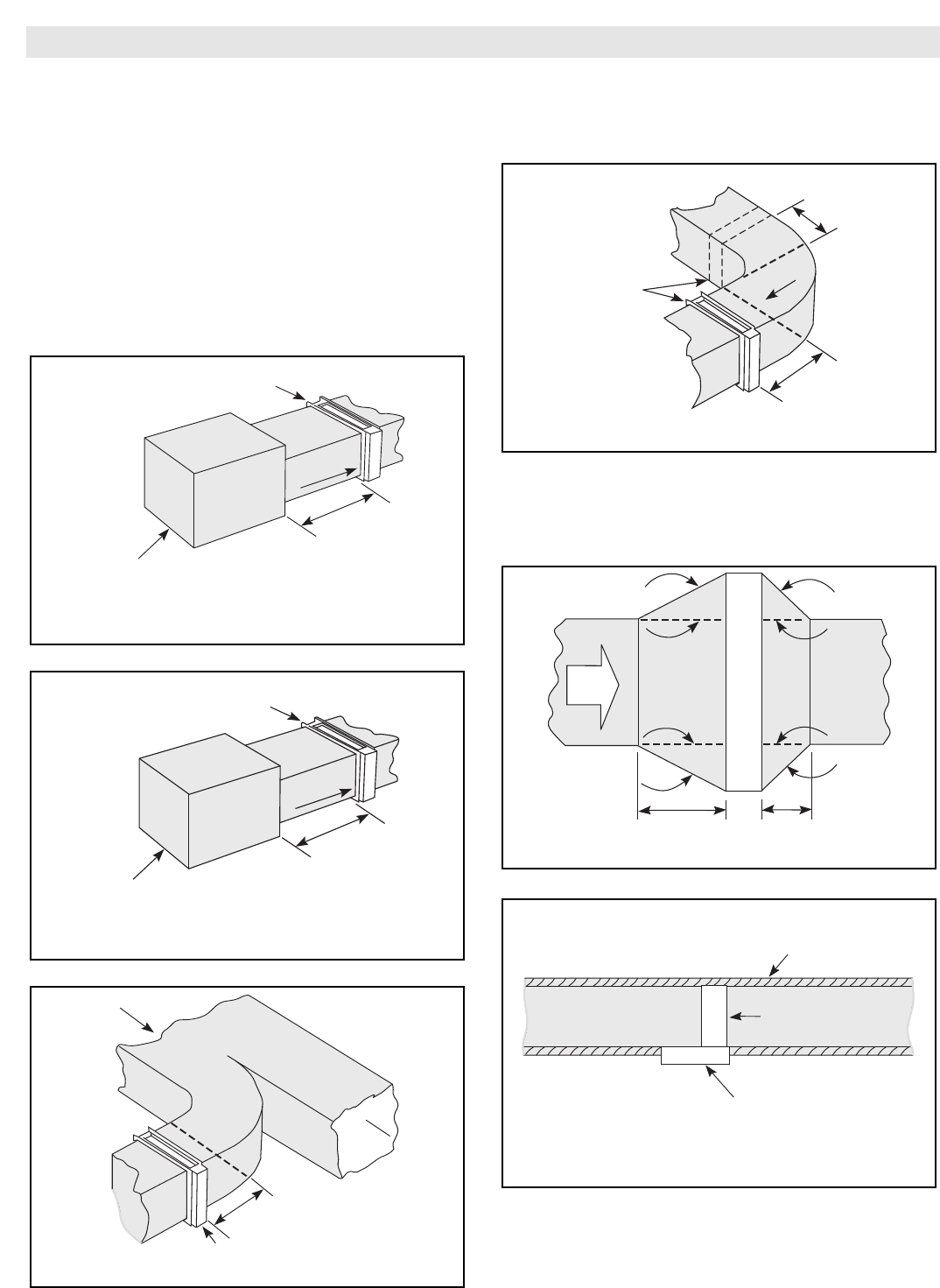
4. Installation near turns. (Refer to Figure 8). If heater must be
installed closer than 4 feet from the downstream side of a turn,
turning vanes must be installed in the turn. The turning vanes
will straighten out the air flow so it will be uniform over the
face of the heater.
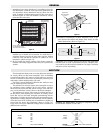
5. Installation with duct transitions in some air distribution sys-
tems, the duct heater may be considerably larger than the duct-
work and the duct area must be increased by a sheet metal tran-
sition. The slope of the transformation piece on the upstream
side of the equipment is limited to 30° as indicated in Figure 9.
On the leaving side, the slope should not be more than 45°.
6. Do not insulate control or terminal box. (Refer to Figure 10).
Leave Control
Box Uninsulated
External
Insulation
Top of Duct
Duct Heater
Air
Flow
30"
Max.
45°
45°
30°
4 Ft. Min.
4 Ft. Min.
Max.
Duct Heater
4 Ft.
Min.
Duct Heater
Here or Here
2 Ft.
Min.
Air Flow
Duct Heater
4 Ft. Min. Straight Section
Air Flow
Duct Heater
4 Ft.
Min.
Air Handler
Air
Flow
Duct Heater
4 Ft.
Min.
Heat Pump,
Central Air Conditioner,
Filters or Humidifier
Air
Flow
-2-
Figure 5
Figure 8
Figure 9
Figure 6
Figure 10
Figure 7