


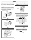
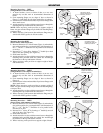

7. Installation in duct larger than heater. For installation where the
duct dimensions exceed the insert type heater dimensions, the
area beyond the heater dimensions must be filled with wire
mesh, expanded or perforated sheet metal of 50% open area as
shown in Figure 11. This will maintain a uniform air velocity
across the face of the duct.
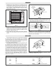
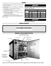
8. Installation with flexible duct. Where a duct heater must be
installed near a flexible duct connection, be certain that a 4’
minimum distance between the duct heater and the flexible
connector exists and that the connector is suitable for 195°F
temperature. (Refer to Figure 12).
9. Do not install duct heater outdoors. Duct heaters cannot be
installed with rooftop equipment where they are exposed to the
weather.
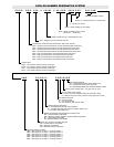
10. Installation with dampers or filters. Maintain at least 4’ dis-
tance between duct heater and damper, filter frames, or other
similar obstructions. (Refer to Figure 13).
Clearance: Zero clearance between duct heater and combustible
materials such as wood is permissible. However, adequate clear-
ance must be provided around terminal box for proper ventilation
and future service accessibility.
4 Ft.
Min.
Damper
Air Flow
Top of Duct
Duct
Heater
4 Ft.
Min.
Air
Flow
Duct Heater
Flexible Duct
(Must be suitable
for 195°F)
Inner Baffle
Insert Type
Duct Heater
Remove Bracket and
Use Sheetmetal Screws
Thru Same Holes into Duct.
Oversized Duct
Perforated Metal
(50% Open Area)
-3-
GENERAL
Flow through duct heater must never drop below the minimum
air velocity shown on duct heater nameplate. If the air handling
system includes filters, they must be cleaned whenever necessary
in order to maintain air flow above the minimum, otherwise poor
temperature control and discomfort will result.
If air flow is poorly distributed within the duct, deflector vanes
must be added to provide correction.
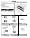
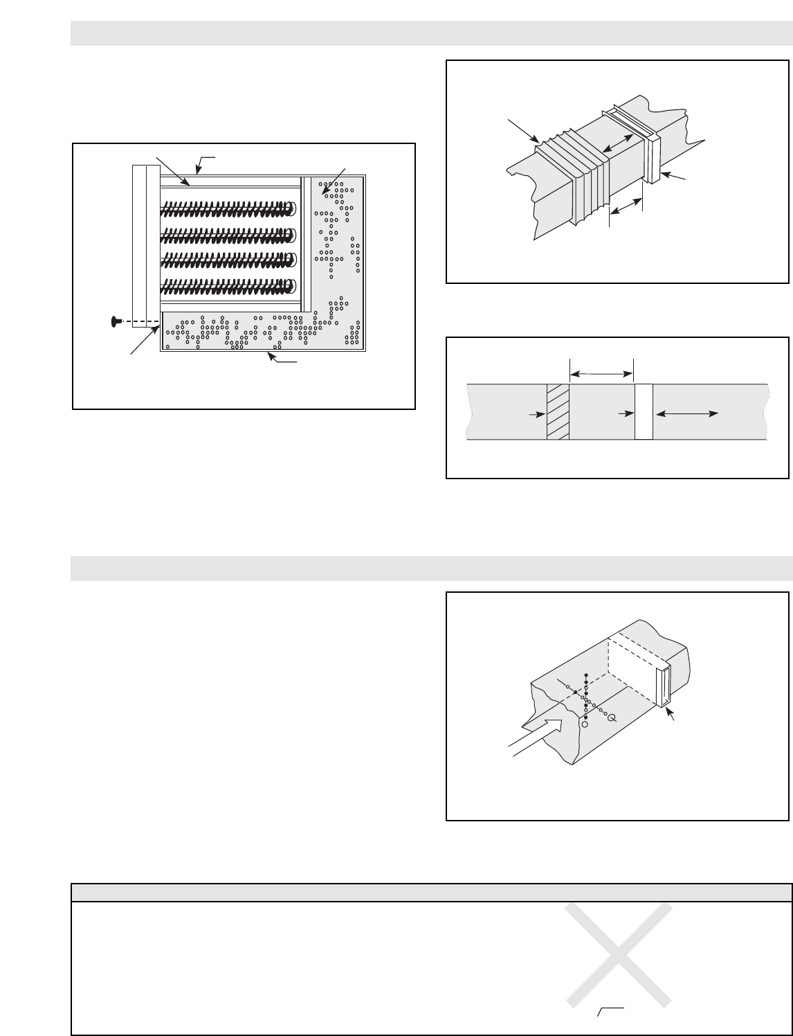
The minimum air velocities shown on the nameplate are not to
be considered average readings. Do not add various velocities
taken across the face of the duct, find an average value, and com-
pare it to the minimum velocity shown on the heater nameplate.
The minimum air velocity refers to any point along the face of
the duct heater when checking duct velocities, no velocity can be
below that sown on the heater nameplate (remembering inlet air
temperature). Velocities are best checked with an anemometer, tak-
ing numerous readings along the horizontal and vertical centerline
of the duct heater at the location prior to installation or slightly up
stream from the heater after installation. (Refer to Figure 14).
Large ducts will require additional readings taken at locations in
addition to the centerline.
Incoming Air Temperature: Incoming air temperature entering
the duct heater must not exceed 100°F.
Duct Heater
Velocity
Profile
Air Flow
AIR FLOW
Example: 500 FT./MIN. Minimum Air Velocity on Heater Nameplate.
600 200x
500 400x
700 800
Velocity 600 Velocity 900
Profile 900 Profile 600
FT./MIN. 700 FT./MIN. 700
600 200x
500 300x
400x
RIGHT: 500 FT./MIN. MINIMUM WRONG: 9 4500 = 500 FT./MIN. AVERAGE
X – below 500 FT./MIN.
Figure 11
Figure 12
Figure 13
Figure 14