


MOUNTING
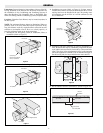
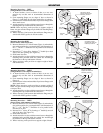
Multiple Duct Heaters: Up to six duct heaters may be combined
into a heating bank as shown in Figure 15. When called for on
order, brackets will be furnished for fastening flange type duct
heaters together to form a bank. Heater will be coded for proper
assembly in the field.
Two to six duct heaters (with flange) may be installed in a hor-
izontal or vertical duct.
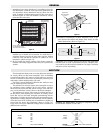
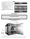
Heaters must be mounted in the position designated by arrows
on the heater frame. (Refer to Figure 16).
The heater terminal box on vertical duct installations can be
located on any side of the duct but for horizontal duct installation
the terminal box must be on the side of the duct.
This heater is not intended for use in hazardous
atmospheres where flammable vapors, gases, liq-
uids, or other combustible atmospheres are pre-
sent as defined in the National Electric Code.
Failure to comply can result in explosion or fire.
HORIZONTAL DUCT — Side terminal
box entry for style DHII & DHIF heaters.
Air flow as shown.
Install with this arrow up.
Mounting Position 4
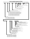
VERTICAL DUCT — side terminal box
entry for style DHRI & DHRF heaters. Air
flow as shown. Install with this arrow up.
Mounting Position 3
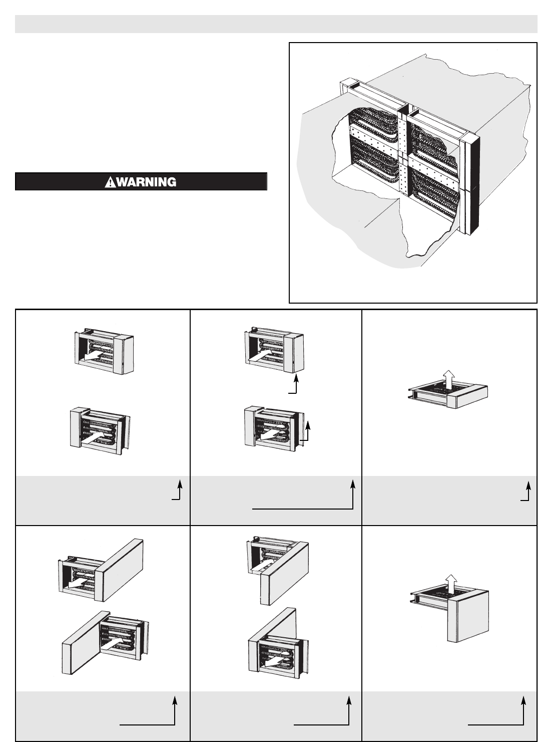
VERTICAL DUCT — Side terminal box
entry for style DHII & DHIF heaters. Air
flow as shown.
Install with this arrow up.
Mounting Position 6
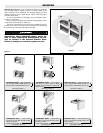
HORIZONTAL DUCT — side terminal
box entry for style DHRI & DHRF
heaters. Air flow as shown. Install with
this arrow up.
Mounting position 2
HORIZONTAL DUCT — Side terminal
box entry for style DHII & DHIF heaters.
Air flow as shown.
Install with this arrow up.
Mounting Position 5
HORIZONTAL DUCT — side terminal box
entry for style DHRI & DHRF heaters. Air
flow as shown. Install with this arrow up.
Mounting Position 1
Figure 16
Figure 15
-4-