


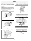
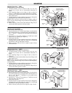

Mounting Procedure — DHIF
(Flanged heaters with control box)
1. At heater location, cut out a section of duct, or a new con-
struction lay out duct work to accommodate dimensions of
heater.
2. Form mounting flanges on cut edges of duct as shown in
Figure 17. Omit flange in side when terminal box overhangs.
3. Position heater in duct and attach duct lip to heater flanges with
sheet metal screws.
4. Attach control box to duct with sheet metal screws through the
mounting holes provided inside the control box.
NOTE: Where necessary, make provision to support weight of
heater. Any part of heater flange may be drilled for attaching hang-
er straps or duct.
5. Where necessary, joint between duct and heater flange may be
sealed with silicone gaskets or silicone sealant.
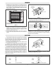
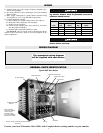
Mounting Procedure DHII
(Insert heaters with control box)
1. Measure dimension “H” of duct heater (Figure 1) and mark the
duct with an outline for a rectangular hole with dimensions of
D-1
1
/2”. The D-1
1
/2” dimension is to be parallel to the direction
of air flow.
2. Increase D-1
1
/2” slot to D by forming a
3
/4” double lip on both
sides of the duct opening. (See Figure 18).
3. Slide heater into duct.
4. Attach control box to duct with sheet metal screws through the
mounting holes provided inside the control box and through
the brackets on the top and bottom of heater.
5. Where necessary, make provision to support weight of heater
and terminal box.
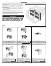
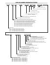
Mounting Procedure — DHRF
(Flanged heaters with compact terminal box)
1. At heater location, cut out a section of duct, or on new con-
struction lay out duct work to accommodate dimensions of
heater.
2. Form mounting flanges on cut edges of duct as shown in
Figure 19.
3. Position heater in duct and attach duct lip to heater flanges with
sheet metal screws.
NOTE: Where necessary, make provision to support weight of
heater. Any part of heater flange may be drilled for attaching hang-
er straps or duct.
4. Attach control box to duct with sheet metal screws through the
mounting holes provided inside the control box.
5. Where necessary, joint between duct and heater flange may be
sealed with silicone gasket or sealant.
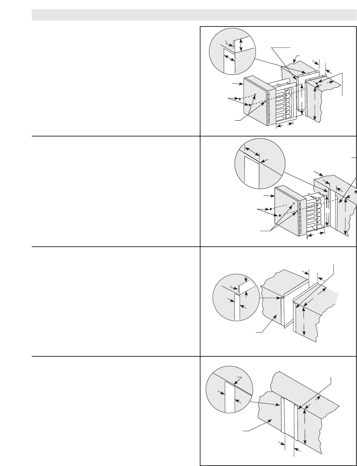
Mounting Procedure — DHRI
(Insert heaters with compact terminal box)
1. Measure dimension “H” of duct heater (Figure 2) and mark the
duct with an outline for a rectangular hole with dimensions of
D-1
1
/2” x “H”. The D-1
1
/2” dimension is to be parallel to the
direction of air flow.
2. Increase D-1
1
/2” slot to “D” by forming a
3
/4” double lip on each
side of the duct. (See Figure 19).
3. Slide heater into duct.
4. Attach control box to duct with sheet metal screws through the
mounting holes provided inside the control box and through
the brackets on the top and bottom of heater.
5. Where necessary, make provision to support weight of heater.
-5-
MOUNTING
Self-Adhesive Gasket
Supplied with Heater and
Installed by Customer
Double
Lip
3/4"
3/4"
Duct
Sheet Metal
Screws
Control
Box
Sheet Metal
Screws
Mounting
Holes
W
W
H
H
D
Self-Adhesive Gasket
Supplied with Heater and
Installed by Customer
Double
Lip
Duct
H
W
3/4"
D
Self-Adhesive Gasket
Supplied with Heater and
Installed by Customer
Double
Lip
3/4"
Duct
Control
Box
Sheet Metal
Screws
Mounting
Holes
W
H
H
W
D
Self-Adhesive Gasket
Supplied with Heater and
Installed by Customer
Double
Lip
3/4"
Duct
D
3/4"
H
W
Figure 17
Figure 18
Figure 19
Figure 20