


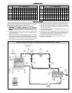
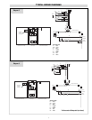
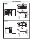
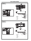
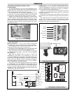
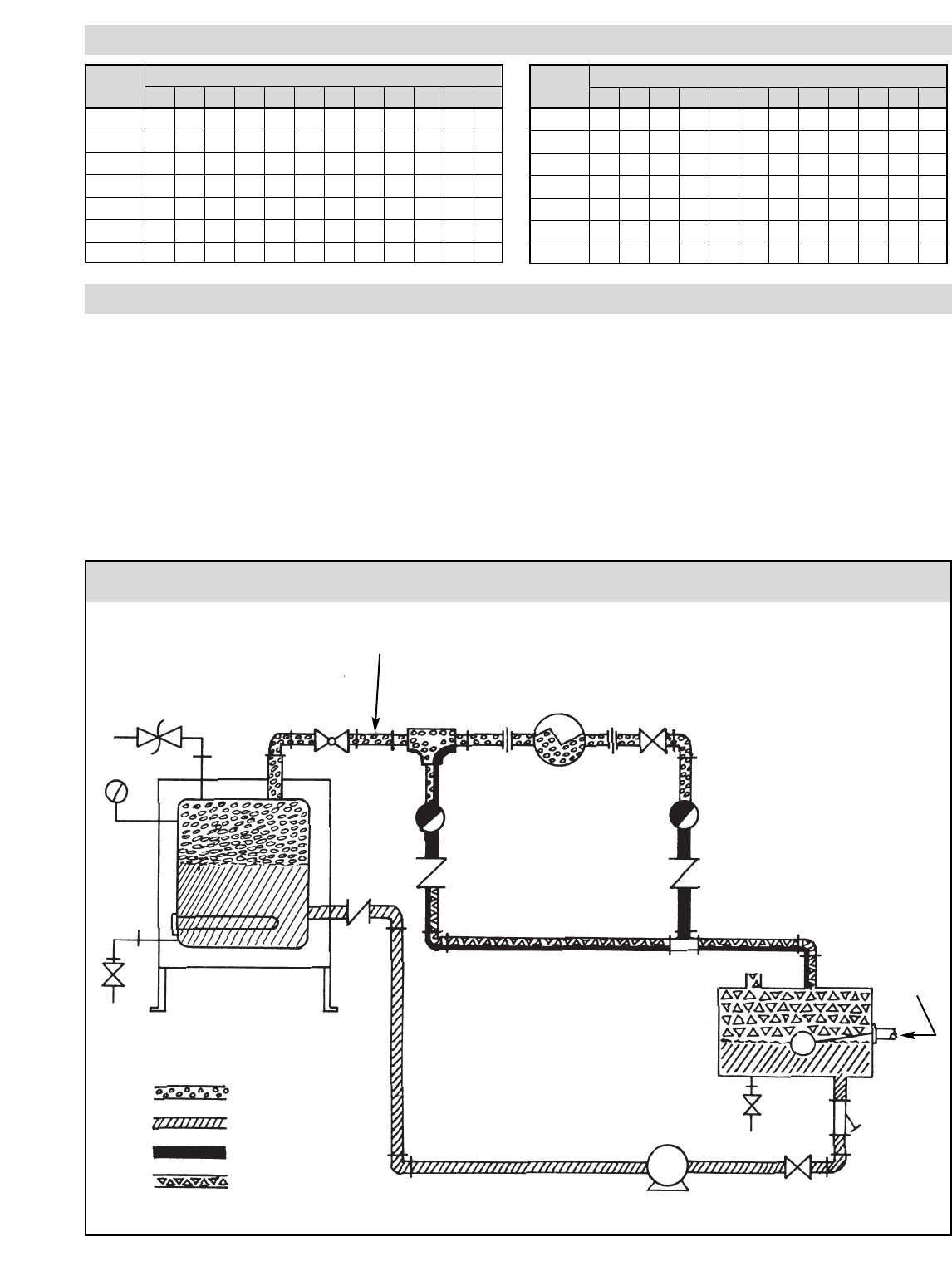
Typical Plumbing Installation of a Steam Boiler with Condensate Return System
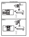
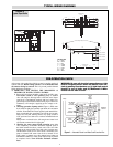
CES — Dimensions (In.)
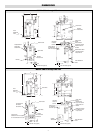
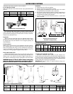
DIMENSIONS
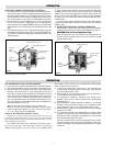
INSTALLATION
Model A B* C D E F G H I J K L
CES-6 37 22-1/2 30 15-1/4 20 30-1/2 9-1/2 16 1/2 1 1/2 1/2
CES-9 37 22-1/2 30 15-1/4 20 30-1/2 9-1/2 16 1/2 1 1/2 1/2
CES-12 37 22-1/2 30 15-1/4 20 30-1/2 9-1/2 16 1/2 1 1/2 1/2
CES-18 37 22-1/2 30 15-1/4 20 30-1/2 9-1/2 16 1/2 1 1/2 1/2
CES-24 43-1/2 26 46 17-1/2 23 34-1/2 16-1/2 24-1/2 1 1 1 3/4
CES-30 43-1/2 26 46 17-1/2 23 34-1/2 16-1/2 24-1/2 1 1 1 3/4
CES-36 43-1/2 26 46 17-1/2 23 34-1/2 16-1/2 24-1/2 1 1 1 3/4
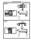
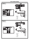
CES — Dimensions (In.)
Model A B* C D E F G H I J K L
CES-48 43-1/2 26 46 17-1/2 23 34-1/2 16-1/2 24-1/2 1 1 1 3/4
CES-60 43-1/2 26 46 17-1/2 23 34-1/2 16-1/2 24-1/2 1 1 1 3/4
CES-72 43-1/2 26 46 17-1/2 23 34-1/2 16-1/2 24-1/2 1 1 1 3/4
CES-100 63-1/2 30 55 21 27 36 16-3/4 37-1/2 1-1/2 1-1/4 1 3/4
CES-135 63-1/2 32 55 20-1/2 26 37-1/2 16 37-1/2 2 1-1/4 1 3/4
CES-160 63-1/2 32 55 20-1/2 26 37-1/2 16 37-1/2 2 1-1/4 1 3/4
CES-180 63-1/2 32 55 20-1/2 26 37-1/2 16 37-1/2 2 1-1/4 1 3/4
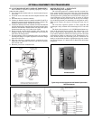
Note: When installing boiler, allow sufficient room (21” minimum) to
facilitate removal of elements if and when necessary.
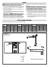
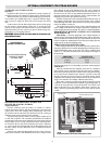
1. The boiler should be mounted on a solid level foundation.
2. WARNING: A minimum distance of 18” between
boiler and any combustible material must be main-
tained.
3. Complete all piping to boiler. Connect water line to tagged fitting
on the motor and pump assembly, if used, or to tagged fitting on
water control feeder.
4. When any type of feed other than a pump feed is used — the exist-
ing water supply must be 10 pounds greater than the boiler operat-
ing pressure to assure water supply maintains proper water level in
boiler. Otherwise, lack of water can cause heater failure. Keep feed
water line valves open at all times except during blowdown.
5. All water feed systems are connected to water inlet check valve.
6. Connect steam line (with Globe valve) to boiler steam outlet.
Valve should be placed as close as possible to boiler outlet and
sized per label on boiler.
7. To insure maximum efficiency of supplied kW, all piping from
outlet should be insulated.
8. Drain and relief valve piping should be in accordance with state
and local codes. Floor drain to be provided directly below unit.
9. All electrical wiring should be done by licensed electrician in
accordance with national and local electrical codes.
10. If pump is located less than 30 feet from boiler, a second
check valve is required.
Vacuum
Breaker
Safety
Valve
Drain
Boiler
Check
Valve
Check
Valve
Check
Valve
Globe
Valve
Gate
Valve
Heat
Exchanger
Water/Steam
Separator
Insulated Steam Lines
(Pitch Down 5˚)
Pitch Down 5˚
Vent
Condensate
Return
Drain
Gate
Valve
Strainer
Return
Cold Water
Make-Up
Centrifugal
Turbine Pump
Steam
Water
Condensate
Vapor
(Typical
Load)
Trap
Trap
3
*Add two inches for transformer.