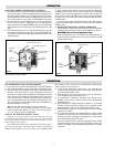
ADJUSTING OPERATING PRESSURE CONTROLS
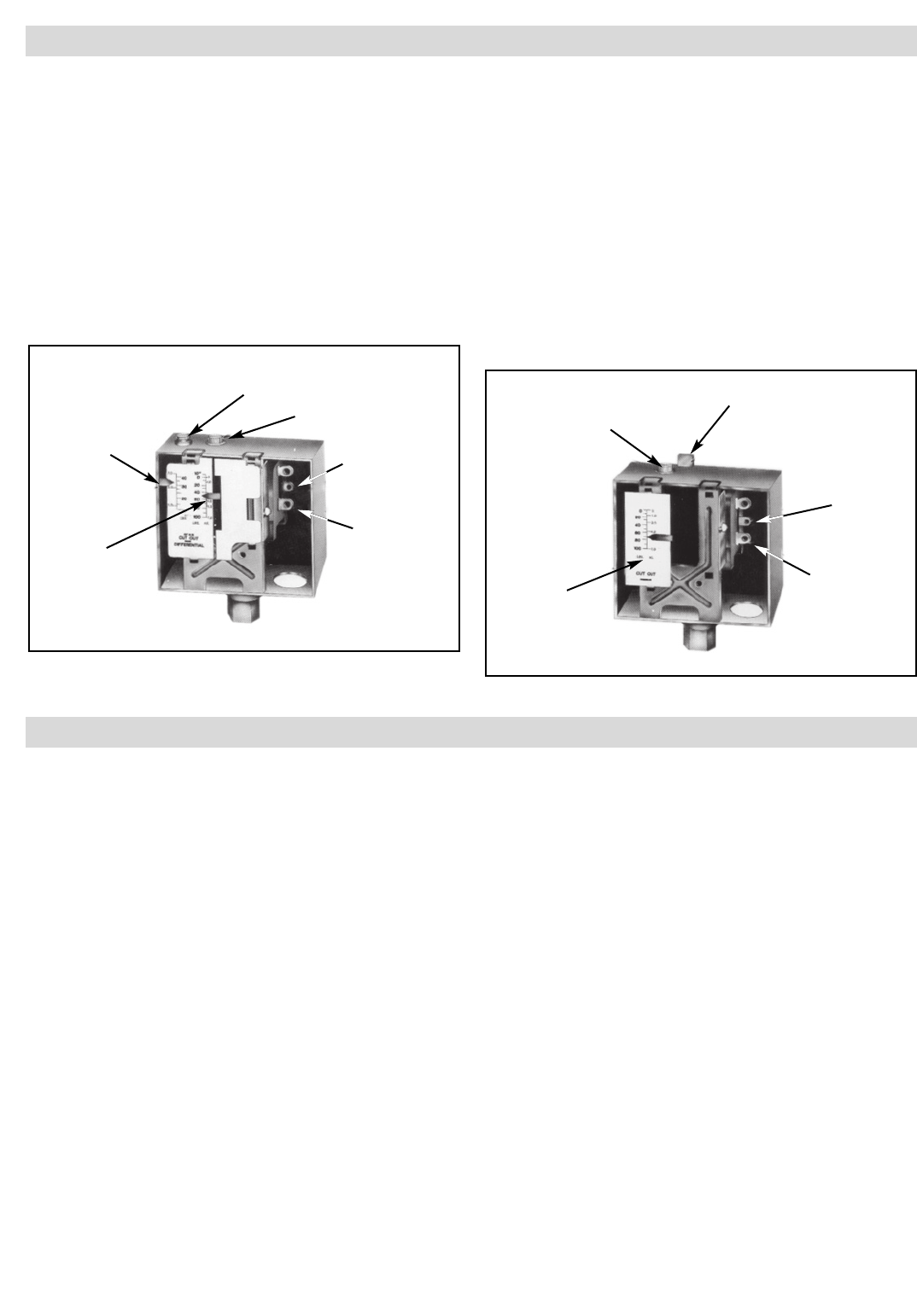
1. Chromalox boilers are supplied with operating and high limit pres-
sure controls. One is used for controlling the operating pressure of
the boiler while the other is used as a high limit control. To deter-
mine the difference in the controls, the high limit has a manual reset
lever on top of the case. Also, there is no differential scale present.
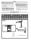
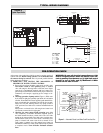
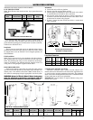
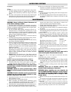
2. On all controls, the pressure adjusting screw on the top of the case
sets the desired pressure. Turning the screw counterclockwise
reduces the pressure setting (CUT OUT) (See Figure 2). High limit
control should be set at 10 psig above the operating pressure of the
boiler.
3. The differential adjusting screw on the operating control is set in the
same manner as the pressure adjusting screw. The CUT OUT set-
ting minus the differential setting, equals CUT IN pressure of the
operating control.
To check operation of the controls, close steam outlet valve and adjust
operating pressure control to a low pressure setting. Also, set high limit
control at 10 psig above operating pressure control. Turn on boiler, and
allow pressure to build up. When pressure gauge reading approaches
set point of pressure control, the switch will trip and shut off boiler.
Turn off boiler.
To reset pressure control, bleed off enough pressure in the boiler by
opening steam outlet drain, or blowdown valve to allow the operating
control to reset.
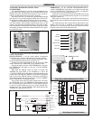
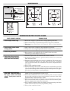
4. HIGH LIMIT PRESSURE CONTROL OPERATION
The high limit is tested in the same manner but with the operating
control set above the pressure setting of the high limit. (Figure 3)
CAUTION: This is for test purposes only!
When the high limit trips, turn off boiler and reset high limit to
proper setting. The manual reset level must be pushed to resume
operation upon startup.
Differential Adjusting Screw
Pressure Adjusting Screw
Terminal 1 Open on
Pressure Rise
Terminal 2
Common
Differential
Setting
Indicator
Pressure
Setting
Indicator
Pressure
Adjusting
Screw
Terminal 1 Open on
Pressure Rise
Terminal 2
Common
Cutout
Pressure
Indicator
Manual Reset Lever
CES-12 through CES-72, one pressure control supplied; CES-100 through CES-
180, two pressure controls supplied.
Figure 2
Figure 1
12
OPERATION
OPERATION
RECOMMENDED START-UP PROCEDURES
1. Close globe valve on steam outlet side of boiler. (Customer Supplied)
2. Turn on boiler and allow pressure to build up to operating pressure.
3. Only open globe valve at quarter turns at first, introducing smaller
amounts of steam into process. Avoid opening globe valve all at
once. This will eliminate the possibility of evacuating the boiler of
water caused by the suddenly increased boiling of the water in the
vessel as the pressure is reduced. On boilers where constant pres-
sure is not maintained, globe valve should be kept partially closed.
This will maintain a constant head on the boiler and stabilize any
fluctuation in boiler water level.
Note: For best boiler performance, a 1/4” less steam valve
than size of safety valve should be plumbed as close as practi-
cable to steam outlet. Where 1/2” safety valve is used on boil-
er, a 1/4” steam valve is recommended.
MANUAL BLOWDOWN INSTRUCTIONS
Blowdown is an essential part of boiler operation. It is the best
preventative maintenance you can give your boiler and will add
years of life to the unit. Make sure a blowdown schedule is estab-
lished and followed regularly.
In extremely hard water areas, blowdown is necessary once a
day. In soft water areas, once each week. If there is a particular
problem which applies to your own local water condition other
than mineral content, take this into consideration in determining
which schedule is to be followed.
1. At end of the working day, while boiler is still operating, turn
switch to the OFF position and close water supply valve. De-ener-
gize wall mounted safety switch.
2. If blowing-down into a receptacle, allow pressure to decrease to
15-20 psi before opening blowdown valve.
3. It is preferable to connect the blowdown valve directly into a
drainage system. If this is done, the boiler can be discharged at
operating pressure.
4. When discharge is complete and boiler is drained — (a) close the
blowdown valve; (b) open water supply valve; (c) put boiler switch
in the ON position; and, (d) close wall mounted safety switch.
5. When refilling is complete, turn off the boiler switch unless further
operation is desirable.
6. If you have been supplied with a Manual Reset Low Water control
as required in some states, the reset button on the control must be
pushed before boiler will begin developing pressure. (Do not push
reset until boiler has filled with water.)
The use of chemical boiler cleaning compounds in these boilers
voids all warranties unless approved by manufacturer. Some com-
pounds will damage copper sheathed heating elements to shorten
useful life.


