


OPTIONAL EQUIPMENT FOR STEAM BOILERS
IF A CONTROLLER SEEMS TO OPERATE IMPROPERLY
If the controller is suspected of operating improperly, it may be
further checked as follows:
1. Leave the controller installed where it is, but disconnect all power
to the boiler.
2. Loosen the cover screw below the main scaleplate and remove the
cover.
3. Disconnect the wires from the controller.
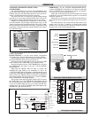
4. Connect an ohmmeter between controller terminals B and W to
measure the resistance of the potentiometer in the controller. The
ohmmeter should read about 135 ohms on an L91B.
5. Connect the ohmmeter between controller terminals W and R and
raise the set point of the controller above the actual pressure being
measured. The ohmmeter should read the full value of the poten-
tiometer measured in step 4 (135 ohms for an L91B).
6. Slowly lower the set point of the controller while observing the
ohmmeter reading. The resistance should drop to zero at some set
point below the actual pressure.
7. An approximation of the proportioning range can be made by
observing the change in set point required for a resistance change
from zero to full value.
8. When the controller is operating properly, reconnect the wires,
replace the cover, tighten the cover screw, and reset the controller
to the desired value.
9. Reconnect power to the controlled motor.
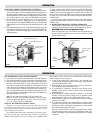
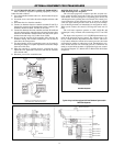
BOILER SEQUENCE — SOLID STATE
Solid State Progressive Sequencer
The solid state progressive sequencer provides accurate elec-
tronic control of multi-stage loads of the type used in Chromalox
steam boilers. It features progressive sequencing (first on-first off)
which equalizes the operating time of each load. This control gives
visual indication of each energized stage by means of integral
solid state light emitting diodes. In the event of power interrup-
tion, all heating elements are immediately de-energized for safety.
When power resumes, the control will restage the loads one at a
time.
The solid state sequencer operates on 120V AC/60 Hz and
each output is relay switched with a load rating of 125 VA at 120V
AC.
The input to the sequencer is a 0-135 OHM potentiometer sup-
plied on the operating pressure control. The sequencer has a sen-
sitivity control which is adjustable from min. to max. This sensi-
tivity control defines the amount of resistance (pressure) deviation
allowed before adding or subtracting a load. Potentiometer resis-
tance should decrease with increasing pressure. Connections are
made to red and white terminals of proportional pressure control.
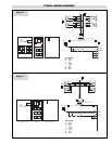
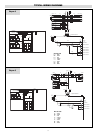
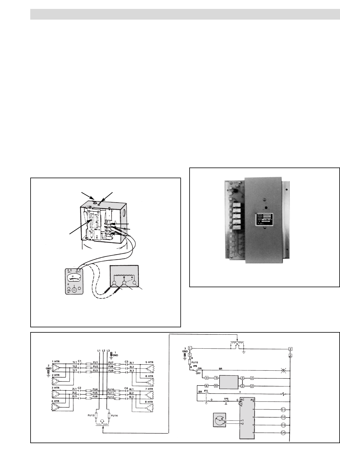
See Wiring Diagram 337-300164-452 for Boiler With Solid State
Sequencer.
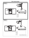
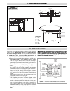
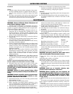
Main Scale
Adjusting
Screw
Proportioning Range
Adjusting Screw
R
W
B
Main Scale
Setting
Indicator
Set Point
Increase
R
W
B
Ohmmeter
Increases to
135 Ohms
Terminals are not Labeled, but Screw-Heads are
Color Coded Red (R), White (W) and Blue (B).
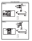
15
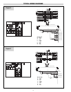
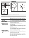
Pressure
Control
5 Step
Control
Sequencer
Auto
Blowdown
System
Heater Contactor
Heater Contactor
Heater Contactor
Heater Contactor
Feed Water
Solenoid Valve
Boiler
On
Optional Transformer
480/120V
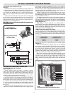
480V 3Ø 60 HZ
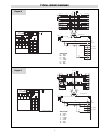
Typical wiring for boilers equipped with Auto Blowdown System and/or
Solid State Sequencer.
Solid State Sequencer