


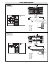
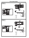
OPTIONAL EQUIPMENT FOR STEAM BOILERS
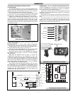
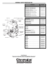
AUXILIARY LOW WATER CUTOFF
Operation
Operation of this control is accomplished by sensing a minute AC
current flowing between submerged contact probe in the boiler shell.
When this minute AC current is conducted through an external cir-
cuit resistance up to 40,000 ohms or less, a signal of sufficient magni-
tude is present to trigger the SCR and, in turn energize the control
relay.
As the water level in the boiler drops below the level of the probe,
the AC current is broken and the control relay is de-energized. The
control will not energize until sufficient water is present in the boiler.
Optional manual reset may require reset prior to heaters being ener-
gized after level 13 brought to normal.
WARNING: Control will not work with de-ionized or de-
mineralized water.
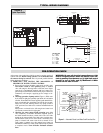
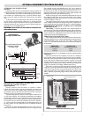
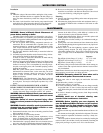
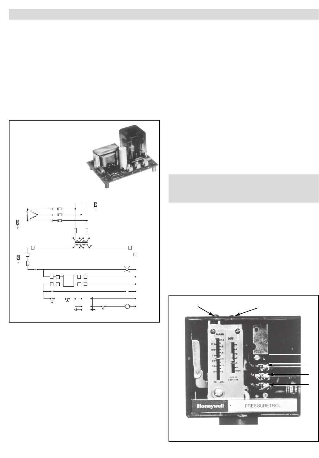
PROPORTIONING PRESSURE CONTROL FOR
SEQUENCER AND SCR CONTROLS
Typical Operation
Pressure variations cause the bellows to expand or contract.
Linkage between the bellows and the potentiometer wiper causes the
wiper to move across the windings on the potentiometer. This varies
the resistance between R and B, and between R and W, causing an
unbalance in the circuit connected to the controller.
A proportioning pressure control is used to regulate a motor driven
or solid state sequencer. The controller potentiometer, the feedback
potentiometer in the motor and a balancing relay in the motor form an
electric bridge circuit. As long as the pressure of the controlled medi-
um remains at the set point of the controller, the circuit is balanced;
i.e., equal currents flow through both sides of the balancing relay and
the relay contacts are open. When the circuit is balanced, the motor
does not run.
If the pressure of the controlled medium rises, the wiper in the con-
troller moves toward W. This unbalances the circuit so a larger current
flows through one side of the balancing relay. The “close” contacts in
the relay make, causing the motor to drive toward its closed position. As
the motor runs, the wiper on the feedback potentiometer moves in a
direction to balance the circuit. When the circuit is again in balance, the
balancing relay contacts open and the motor stops.
Similarly if the pressure of the controlled medium falls, the wiper on
the controller potentiometer moves toward B, and the “open” contacts
in the balancing relay make. The motor drives towards its open position
until circuit balance is achieved.
The slightest change in the pressure of the controlled medium will
cause a change in the number of elements energized to compensate for
it, thus keeping the pressure constant. This process is called modulation.
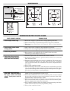
PROPORTIONAL PRESSURE CONTROL ONLY SUPPLIED
WITH SEQUENCER
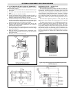
Main Setting — Turn the adjustment screw until the indicator is
opposite the low point of the desired throttling range. That is, if the pres-
sure is to be held at a minimum of 50 psi, set the indicator at 50 psi. The
pressure will them be maintained between 50 psi and a higher pressure
equal to the 50 psi plus the throttling range.
THROTTLING RANGE SETTING (L91B)
After setting the indicator for the minimum pressure, turn the throt-
tling range adjustment screw until the throttling range indicator points to
the desired throttling range on the scale. This scale is graduated from
“min” to “F”. The value of each division varies with the scale range of
the instrument.
PRESSURE VALUE EACH
SCALE RATING DIVISION ON SCALE
0-15 psi 2.2 psi
5-150 psi 3.6 psi
Pressure scale rating will vary depending on pressure control supplied.
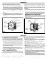
CHECKOUT
After the controller has been installed, wired, and set, it should be
tested with the system in operation. First allow the system to stabilize.
Then observe the operation of the controller while raising and lowering
its set point. Pressure should increase when the set point is raised and
decrease when the set point is lowered. Use accurate pressure testing
equipment when checking out the controller. Do not rely on inexpensive
gauges. The controllers are carefully calibrated at the factory.
If the motor or actuator runs the proper direction when the set point
is adjusted, it can be assumed that the controller is operating properly. If
it runs in the wrong direction, reverse the B and W wires. Observe the
action of the motor to see if it stabilizes. If the motor is moving con-
stantly, widen the proportioning range a little at a time, until the system
is stable.
14
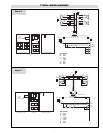
Adjusting Screw
Differential Adjusting Screw
R
W
B
(L91B)
Proportioning Pressure Control used with Sequencer Control
3
3
2
2
2
2
6
6
2
2
1
1
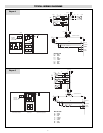
LWCO Probe
Aux. Low
Water Cutoff
O
O
O
R
H
C
1PS
C1
NO
L1 L2
1PS
BL
W
Y
2PS
BL
Auto
Blow
Down
System
BR
C1
W
W
Heater
Contactor
Feed Water
(Solenoid Pump)
R
1LT
W
Boiler On
2
GND
3
GND
1
GND
B
FU3
B
1PB On
Off
X1
X3
X2 X4
1 HTR
C1
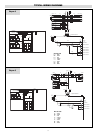
Fuses Supplied
on Boilers Rated
Over 40 Amps.
FU
FU
FU
FU2
FU1
H1 H2H3 H4
480V/120V
1.5 KVA
480V
3
60 HZ
L1 L3
L2
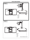
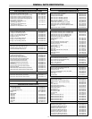
Typical Wiring for
Auxiliary Low Water Cutoff
Electronic Resistance Sensing
Amplifier for Auxiliary
Low Water Cutoff