


Installation Instructions Model PNR™
7
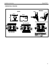
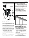
Mount the Display
1. Make sure power is not supplied (turned off) to the
display before attempting to mount the display.
2. Following the instructions for mounting the PSB
interface bracket of your specific plasma display
panel, install the mounting bracket on your plasma
display panel.
WARNING: Watch for pinch points. Do not put your
fingers between movable parts.
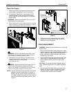
3. While supporting both sides of display, align four mounting
buttons on display or interface bracket with four mounting
holes in head assembly. (See Figures 6 and 7)
Figure 6
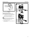
WARNING: DISPLAY MAY WEIGH IN EXCESS OF 40
LBS! Always use two people and proper lifting techniques
when installing or positioning display on stand.
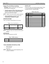
4. Lower display into place listening for audible "click" to
ensure recessed area of mounting buttons are properly
seated in lower area of mounting holes.
(See Figures 6 and 7)
WARNING: IMPROPER INSTALLATION CAN LEAD TO
DISPLAY FALLING CAUSING SERIOUS PERSONAL
INJURY OR DAMAGE TO EQUIPMENT! Ensure mounting
buttons are completely engaged in mounting holes.
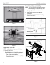
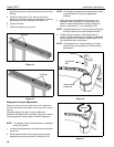
NOTE: Holes are provided in the faceplate for use with a
padlock or similar locking device, if desired. In
addition, the pin and nut may be removed from
the upper holes and moved to the lower holes for
use as a more permanent locking device. (See
Figure 7)
Figure 7
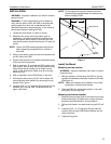
5. Connect and secure power/audio/video cables,
making sure to leave sufficient slack to allow for
movement of the swing arms.
CABLE MANAGEMENT
WARNING: Make sure your cables do not run through
a pinch point.
1. Route power/audio/video cables through the cable
channel in top arm (see Figure 8), allowing sufficient
slack in cables for extension and avoiding pinch
points, and secure cables using two clips and two
tiewraps (50, not shown).
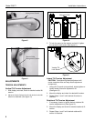
2. Route power/audio/video cables along bottom arm
(see Figure 9), using tiewraps (50, not shown) to
secure cables to each arm, and through cable
channel.
CAUTION: To prevent equipment damage, do not
route cables through holes in the display mounting
plate.
3. Route power/audio/video cables to an open area
behind the mounting plate (not shown). Leave a
sufficient amount of slack in cables to allow for
connection and extension where needed.
3
5
4
Remove pin
and nut and
move to lower holes
A padlock or bolt may
be placed through latch
holes