


Model PNR™ Installation Instructions
10
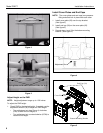
bottom) and secure using two bolts (one top and one
bottom).
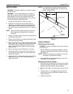
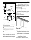
5. Install four bolts (two on the top and two on the
bottom) to secure the swing arm assembly to the top
and bottom mounting brackets (See figure 14).
6. Tighten the bolts.
7. Install the display on the mount.
Figure 14
Figure 15
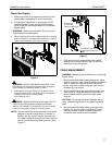
Swing Arm Tension Adjustment
Swing arm tension is pre-set at the factory and is adjusted to
accommodate displays with weights near the top of the mounts
capacity.
If smaller displays are used it may be difficult to
reposition the display after mounting. Swing arm tension
can be adjusted to compensate for smaller display by:
NOTE: The display must be mounted prior to adjusting
swing arm tension.
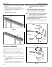
1. Locate the adjustment bar and wrench provided with
the mount.
2. Place adjustment bar into socket head cap screw
located at swing arm pivot point. (See figure 16)
NOTE: The display may need to be repositioned in order
to gain access to the tension adjustment
screw(s).
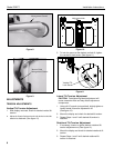
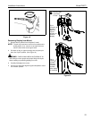
3. Using the wrench provided with the mount, turn
adjustment bar clockwise to increase swing arm
tension or counterclockwise to reduce swing arm
tension. (See figure 17) and (See figure 18)
NOTE: Small adjustments of 1/8 turn or less are typically
all that is required to achieve desired tension.
4. Check swing arm tension. If desired tension is
present, tension adjustment is complete. If additional
tension adjustment is required, repeat steps 2 and 3
until desired tension is achieved.
NOTE: If changing from a smaller display to a larger
display it may be necessary to increase swing
arm tension.
Figure 16
Figure 17
Top Bolts
Top Bolts
Adjustment
Bar
Wrench
Socket Head
Capscrew
Reduce