


Page 9SKU 93188 For technical questions, please call 1-800-444-3353
OPERATING INSTRUCTIONS
The following sections describe the operational components and controls of the Drain
Cleaner, as well as its operation and application.
Operational Components and Controls
Warning: Do not allow your hands, clothing or any other object to become caught
between the belt and the drum. Serious personal injury could result.
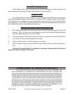
The main operational components of the Drain Cleaner tool are the Motor (7), with its 1.
Motor Direction Switch (5), Foot Switch (14) and the Cable Feed Unit (44a) with its
direction controller.
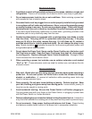
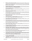
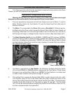
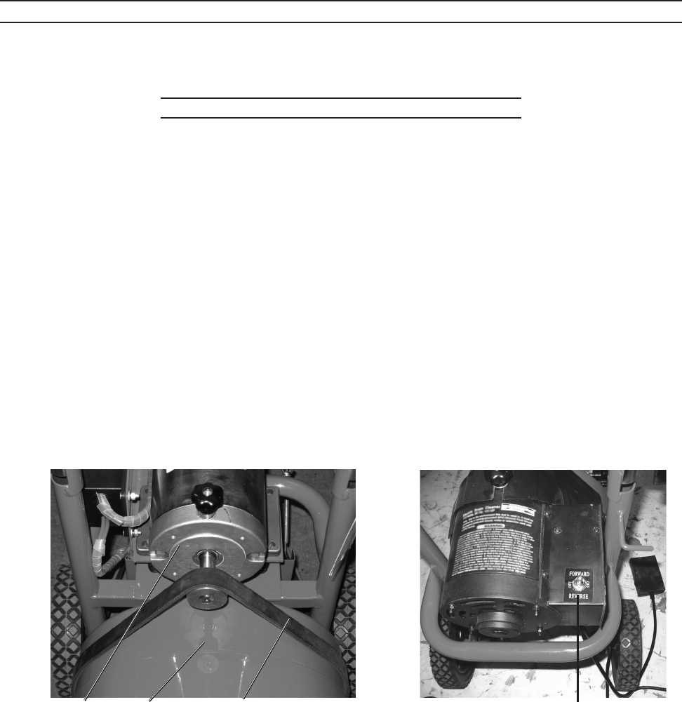
The 2. Motor (7) is connected to the Drum (38a) using a Drive Belt (2). When turned on,
the Motor turns the Drum, which causes the Spring Cable (39a) to rotate. Rotation of
the Spring Cable helps it to move through bends or turns in the drain line, and also to
drill through soft clogs, or entangle harder clogs for removal. (See photo below, left.)
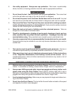
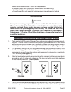
The 3. Motor Direction Switch (5) has NORMAL, UNBIND and OFF settings. NORMAL
will set the Spring Cable to rotate clockwise (viewed from machine rear), causing it to
bore into or entangle any obstruction. UNBIND will cause the Spring Cable to rotate
counterclockwise (viewed from machine rear), causing it to unwind from any obstruc-
tion. (See photo below, right.)
Motor (7), Drum (38a) and Drive Belt (2). Motor Direction Switch (5)
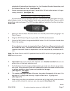
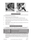
The Motor is controlled by a 4. Foot Switch (14). Whenever the Motor Direction Switch
(5) is in the NORMAL or UNBIND position, stepping on the Foot Switch (14) will cause
the motor to run and the Drum (38a) to turn. NOTE: The Foot Switch is in a rubber boot
to make it water-resistant. (See photo on page 10, top-left.)
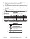
The rotating Drum causes the Spring Cable (39a) to rotate along its axis like a drill. 5.
The Direction Lever (44-16) on the Cable Feed Unit (44a) controls the motion of the
Spring Cable (39a) forward into the drain or back into the Drum (38a). The feed tension
is control by the Star Knob (44-13). See photo on page 10, top-right. The Star Knob
(44-13) must be loosened before changing the position of the Direction Lever (44-16),
and then retightened after the adjustment.