


4-GB
4
Install Door Control
Locate door control where the garage door is visible, away from
door and door hardware and out of the reach of children. Mount
at least 1,5 m (5 feet) above the floor
Serious personal injury from a moving garage door may result
from misuse of opener. Do not allow children to operate the door
control or remote control transmitter.
Permanently fasten the caution label permanently to the wall near
the door control as a reminder of safe operating procedures.
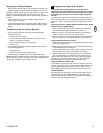
There are 2 screw terminals (1) on the back of the door control (2).
Strip about 6mm (1/4") of insulation from bell wire (4). Separate wires
enough to connect the white/red wire to RED terminal screw 1 and the
white wire to WHT terminal screw 2.
Fasten the door control to an inside garage wall with sheet metal
screws (3) provided. Drill 4mm (5/32") holes and use anchors (6) if
installing into drywall. A convenient place is beside the service door
and out of reach of children.
Run the bell wire up the wall and across the ceiling to the garage door
opener. Use insulated staples (5) to secure wire. The receiver quick
connect terminals are located behind the light lens of the opener.
Connect the bell wire to the terminals as follows: white/red to red (1)
and white to white (2).
Operation of the Door Control
Press to open or close door. Press again to stop door while moving.
21
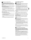
21A. Using Multi-function Door Control: Press push bar (1) to open
or close door. Press again to stop door while it is moving.
Light Feature: Press Light button (2) to turn opener light on or off. If
you turn it on and then activate opener, light will remain on for 2-1/2
minutes. Press again to turn it off sooner. Light button will not control
the opener lights when door is in motion.
Lock Feature: Prevents operation of door from portable remote
controls. However, door will open and close from Door Control push
button, Outside Keylock and Keyless Entry Accessories.
• To Activate: Press and hold Lock button (3) for 2 seconds. Push
button light will flash as long as Lock feature is on.
• To turn off: Press and hold Lock button (3) again for 2 seconds. Push
button light will stop flashing. Lock feature will also turn off whenever
“LEARN” button on opener control panel is activated.
114A2804E-GB
Install the Protector System™
In order to operate this unit, the Protector System™ MUST be
installed.
The Protector System™ provides an additional measure of safety
against a small child being caught under a garage door.
It uses an invisible beam which, when broken by an obstruction,
causes a closing door to open and prevents an open door from closing
and is strongly recommended for homeowners with young children.
22
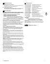
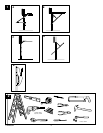
Installing the Brackets
Be sure power to the opener is disconnected.
Install and align brackets so sensors will face each other across
garage door, with beam no higher than 6" (15 cm) above floor. They
may be installed in one of three ways, as follows.
A. Garage door track installation (preferred):
• Slip curved arms over rounded edge of each door track, with curved
arms facing door (1). Snap into place against side of track (2). It
should lie flush, with lip hugging back edge of track.
If your door track will not support bracket securely, wall installation is
recommended.
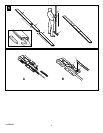
B. Floor installation (Figure 4):
• Use wood blocks or extension brackets (See Accessories) to
elevate sensor brackets so lenses will be no higher than 6"
(15 cm) above floor (1).
• Carefully measure and place right and left assemblies at same
distance out from wall. Be sure all door hardware obstructions are
cleared.
• Fasten to floor with concrete anchors as shown (2).
C. Wall installation (Figure 2 & 3):
• Place bracket against wall with curved arms facing door (1). Be
sure there is enough clearance for sensor beam to be unobstructed.
• If additional depth is needed, an extension bracket (See
Accessories) or wood blocks can be used (2).
• Use bracket mounting holes as a template to locate and drill (2)
3/16" diameter pilot holes on wall at each side of door, no higher
than 6" (15 cm) above floor (3).
• Attach brackets to wall with lag screws (Not provided).
• If using extension brackets or wood blocks, adjust right and left
assemblies to same distance out from mounting surface. Make sure
all door hardware obstructions are cleared.
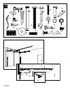
D. Mounting and Wiring the Safety Sensors
Slide a 1/4"-20x1/2" carriage bolt head into slot on each sensor (1).
Use wing nuts to fasten sensors to brackets, with lenses pointing
toward each other across door (2). Be sure lens is not obstructed
by a bracket extension (3).
• Finger tighten wing nuts.
• Run wires from both sensors to opener. Use insulated staples to
secure wire to wall and ceiling.
• Strip 7/16" (11 mm) of insulation from each set of wires (4).
Separate white and white/black wires sufficiently to connect to
opener quick-connect terminals. Twist like colored wires together
(5). Insert wires into quick-connect holes: white to white (3) and
white/black to grey (4).