


7-GB
7
114A2804E-GB
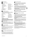
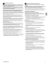
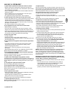
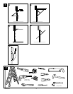
Accessories
(1) Model 84330EML Single-Function Remote Control
(2) Model 84333EML 3-Function Remote Control
(3) Model 84335EML 3-Function Mini Remote Control
(4) Model 8747EML Keyless Entry System
(5) Model 845EML Multi-Function Door Control Panel
(6) Model 760EML Outside Keylock
(7) Model 1702EML Outside Quick Release Lock
(8) Model 770EML The Protector System™
(9) Model 1703EML The Chamberlain Arm™
(10) Model FLA230EML Flashing Light Kit
(11) Model 75EML Lighted Door Control Button
(12) Model 1EML Door Handle Quick Release
(13) Model 34EML 2-Position Key Switch (Flush Mount)
Model 41EML 2-Position Key Switch (Surface Mount)
NOT SHOWN
Model MDL100EML Mechanical Door Latch Kit
WIRING INSTRUCTIONS FOR ACCESSORIES
Outside Keylock – To opener terminals: Red-1 and White-2
Protector System™ – To opener terminals: White-3 and Grey-4
Door Control Panel – To opener terminals: Red-1 and White-2
30
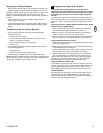
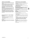
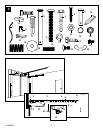
Replacement Parts
31 32
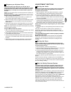
Special Features
A. Door within a door connection
Open light lens. Locate auxiliary quick connect terminals. Insert
bell wire into quick connect terminals 8 and 7
B. Flashing light connection
The flashing light can be installed anywhere. Connect light leads
to quick connect terminals 6 and 5. Terminal 5 is ground.
28
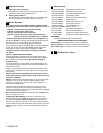
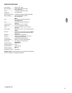
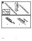
Quick Release
As you proceed with the installation of Model 1702EML Outside
Quick Release, refer to door types shown in Figures A, B, C and D:
Figure A: One-piece door with horizontal track only
Figure B: One-piece door without track
Figure C: Sectional Door with curved track
Figure D: Canopy and one-piece door with horizontal and
vertical track with “The Chamberlain Arm” installed
Locate the Quick Release on the outside of your garage door (2).
For doors A, B and C, center the Quick Release (1) below the opener
door bracket (3). For door style D, locate Quick Release (1)
approximately 10cm on either side of the door’s centerline.
For one-piece doors without track (B), position lock 35-60cm below top
of door. For all other door types (A, C and D), position the lock 50-
75cm below the top of the door (refer to illustrations). If door
construction is metal, refer to special instructions contained in
the "NOTE".
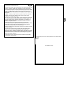
Figure E – Install Outside Quick Release:
Fasten template G at marked location. From outside of door, drill a
19mm diameter hole for the lock (1) and two 6,5mm side holes (2) for
the 1/4"-20x2-1/2" mounting bolts (4). Drill all holes completely
through the door.
Uncoil cable attached to end of tumbler. Guide cable (3) through the
19mm diameter hole from outside the door. Insert lock assembly and
position flush with door.
Insert the two mounting bolts into the side holes from outside of door.
Fasten from the inside with 1/4" washers (5) and hex nuts (6). Tighten
nuts securely.
NOTE: On a metal door, the template must be positioned so that
all the drilled holes will pass through the inside reinforcement stile
of the door, if possible.
Figure F – Remove rope from trolley release arm (1). Place free cable
loop (2) over one pin of the master link outside bar (3) as shown.
Securely tie a loop (4) at free end of release rope and place over
second pin in outside bar (5).
Push pin holding cable loop through hole in the release arm of the
trolley. Push cap (6) onto the pins and into pin notches (7). Be sure
cable loop and manual rope are secured to pins. Slide clip-on spring (8)
over cap and lock onto pin notches.
Refer to Figures A, B, C and D; use plastic ties (4) to loosely secure
the excess cable to door arm.
To Operate the Quick Release: Insert the key into lock and turn
clockwise. Remove the key AND tumbler from the lock. Pull firmly on
the cable. Do not pull on the key or tumbler. The outer trolley will
disconnect from the inner trolley so the door can be opened manually.
Trolley sections will reconnect automatically when the opener is started.
Replace tumbler in the lock. Turn the key counterclockwise. Remove
the key.
29