


2-GB
2
ASSEMBLY SECTION
IMPORTANT: If you have a canopy door, you need to use the
instructions packed with The Chamberlain Arm™ Accessory in
conjunction with this Owner's Manual when assembling the rail.
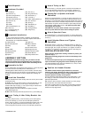
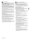
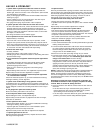
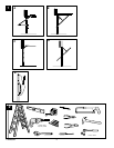
Completed Installation
As you proceed with the assembly, installation and adjustment
procedures in this manual, you may find it helpful to refer back to
this illustration of a completed installation.
(1) Header Sleeve
(2) Idler Pulley Bracket
(3) Trolley
(4) Rail
(5) Chain/Belt
(6) Hanging Bracket
(7) Power Cord
(8) Opener
(9) Light Lens
(10) Manual Release
Rope & Handle
(11) Curved Door Arm
(12) Straight Door Arm
(13) Door Bracket & Plate
(14) Header Bracket
(15) Trolley Release Arm
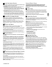
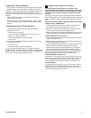
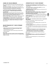
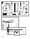
(1) Hex Bolt (4)
(2) Clevis Pin (1)
(3) 8mm Carriage Bolt (3)
(4) Wood Screws (8)
(5) Sheet Metal Screws (2)
(6) Clevis Pin (2)
(7) Rope
(8) Handle
(9) Insulated Staples (10)
(10) Anchor (2)
(11) Concrete Anchor (6)
(12) Lock Washer (7)
(13) Hex Nut (7)
(14) Ring Fastener (3)
(15) Rail Grease (1)
(16) Lock Nut (1)
(17) Metric Tapping Screw (4)
(18) Hex Screw (3)
(19) Spring (1)
(20) Flat Washer (2)
(21) Stop Bolt (1)
(22) Carriage Bolt (2)
(23) Wing Nut (2)
Hardware Provided
3
4
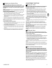
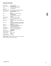
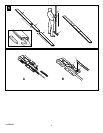
Assemble the Rail
Grease inside edges of rail sections using grease (1). Place rail pieces
(2) on flat surface for assembly. All four rail sections are
interchangeable. Slide rail brace (3) onto rail section. Connect rail by
sliding rail brace onto next rail section. Tap rail assembly (4) on piece
of wood (5) until rail sections are flush. Repeat with remaining rail
sections.
5
Install the Chain/Belt
Remove chain/belt from carton and lay chain out on floor (do not allow
chain/belt to twist).
A. Chain: Push pins of master link bar (3) through chain link (4) and
hole in back end of trolley (5). Push cap (2) over pins and onto
notches. Slide clip-on spring (1) over cap and onto pin notches until
both pins are securely locked in place.
NOTE: If needed, use chain extension link parts to increase
chain/cable length (6A).
B. Belt: Hook the trolley connector (6) into the slot (7) on the trolley (8).
6
Attach Trolley to Rail
Slide outer trolley (1) into back (opener) end of the rail assembly (2),
be sure end with trolley release arm (3) is heading in direction of
opener. Slide outer trolley down rail until it engages with inner trolley.
8
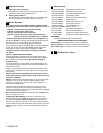
Fasten Rail to Opener and Install
Chain/Belt
Remove four washered bolts (1) from top of opener. Place rail (2) on
opener, flush with stop (3) on top of opener. Wrap chain/belt (4) over
sprocket (5). Push idler pulley bracket assembly toward front of the rail
to eliminate excess slack in chain/belt. Align bolt holes on brackets (6)
with bolt holes on opener. Secure brackets to opener with previously
removed bolts. Tighten bolts securely. The opener sprocket teeth
must engage the chain/belt.
CAUTION: Use only those bolts mounted in the top of opener.
Use of any other bolts will cause serious damage to opener.
9
Attach Sprocket Cover
Place sprocket cover (1) on top of the opener (2), secure with screws
(3). Insert stop bolt (4) into trolley stop hole (5), secure with washer (6)
and nut (7).
10
Install Header Sleeve and Tighten
Chain/Belt
Slide header sleeve (1) onto rail (5). Slide flat washer (3), spring (2)
and washer (3) onto carriage bolt (4). Thread nut (6) onto carriage bolt
until finger tight. Use an open end wrench (7) to tighten nut until the
chain/belt is not against the inside surface of the rail. See image (8).
11
INSTALLATION SECTION
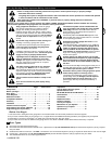
Wear protective goggles when working overhead to protect your
eyes from injury.
Disengage all existing garage door locks to avoid damage to the
garage door.
To avoid serious personal injury from entanglement, remove all
ropes connected to the garage door before installing the opener.
It is recommended that the opener be installed 2,1m (7 feet) or more
above the floor where space permits.
Position the Header Bracket
The header bracket must be rigidly fastened to a structural
support of the garage. Reinforce the wall or ceiling with a 40 mm
(1-1/2") board if necessary. Failure to comply may result in
improper operation of safety reverse system.
You can attach the header bracket either to the header wall (1) or to
the ceiling (3). Follow the instructions which will work best for your
particular requirements.
With the door closed, mark the vertical centerline (2) of the garage
door. Extend line onto header wall above the door.
Open door to highest point of travel. Draw an intersecting horizontal
line (4) on header wall 5 cm (2") above high point to provide travel
clearance for top edge of door.
12
Tools Required
2
114A2804E-GB
Insert Trolley & Idler Pulley Bracket into
Rail
Slide idler pulley bracket (1) and inner trolley (2) into back (opener)
end of rail assembly (3), be sure to insert idler pulley bracket as
shown. Arrow on trolley (7) must face toward front (header) end of rail
(4). Push idler pulley bracket toward front (header) end of rail (4).
Insert carriage bolt (5) into bolt cut out in the idler pulley bracket (6).
7