


8
ENTRAPMENT PROTECTION ACCESSORIES
(OPTIONAL)
PHOTO EYES & SENSING EDGES
Sensing devices provided for door industry type operators with an
isolated normally open (N.O.) dry contact output are compatible
with your operator. This includes pneumatic and electric edges,
and through beam and retro reflective photo eyes. If you would
like to order or receive more information on safety devices, please
contact your local Authorized Dealer.
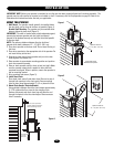
If not pre-installed by the door manufacturer, mount the sensing
edge on the door according to the instructions provided with the
edge. The sensing edge may be electrically connected by either
coiled cord or take-up reel.
Important Notes:
a. Proceed with limit switch adjustments described below before
making any sensing edge wiring connections to operator.
b. Electrician must hardwire the junction box to the operator
electrical box in accordance with local codes.
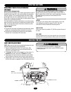
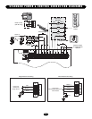
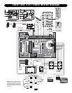
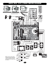
WIRING
For wiring of your sensing device to the operator, refer to the
wiring diagrams provided on pages 13 and 14. See field
connection terminals identified as Reversing Device.
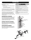
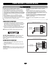
TAKE-UP REEL
Take-up reel should be installed 12" (30.48 cm) above the top of
the door.
COIL CORD
Connect operator end of coil cord to junction box (not provided)
fastened to the wall approximately halfway up the door opening.
ADJUSTMENT
To avoid SERIOUS personal INJURY or DEATH from
electrocution, disconnect electric power BEFORE manually
moving limit nuts.
WARNING
CAUTION
WARNING
WARNING
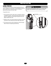
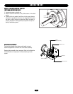
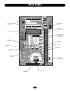
LIMIT SWITCH ADJUSTMENT
NOTE: Make sure the limit nuts are positioned between the limit
switches before proceeding with adjustments.
1. Depress retaining plate to allow nut to spin freely. After
adjustment, release plate and move nut back and forth to
ensure it is fully seated in slot.
2. To increase door travel, spin nut away from limit switch. To
decrease door travel, spin limit nut toward limit switch.
3. Adjust open limit nut so that door will stop in open position
with the bottom of the door even with top of door opening.
4. Repeat steps 1 and 2 for close cycle. Adjust close limit nut so
that the limit switch is engaged as door fully seats at the floor.
CLOSE OPEN
CLOSE Limit Switch
OPEN Limit Switch
SAFETY
(Aux. Close) Limit Switch
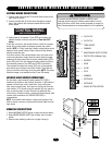
INSTALLATION
To reduce the risk of SEVERE INJURY or DEATH, ALWAYS
install reversing sensors when the 3-button control station is
out of sight of door or ANY other control (automatic or manual)
is used. Reversing devices are recommended for ALL
installations.
WARNING
CAUTION
WARNING
WARNING