


11
CONTROL STATION WIRING AND INSTALLATION
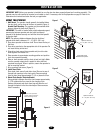
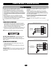
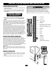
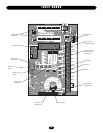
CONTROL WIRING CONNECTIONS
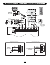
1. Connect control wires to the P1 terminal block located on the
logic board as shown.
2. Connect conduit with all control wires through the conduit
hole in the electrical box enclosure marked with the label
shown below.
3. Apply power to the operator. Press OPEN push button and
observe direction of door travel and then Press the STOP
button.
If door did not move in the correct direction, check for improper
wiring at the control station or between operator and control
station. NOTE: In “Diag” mode the 3-button control station can be
tested to verify correct wiring of Open, Close and Stop buttons
without moving the door.
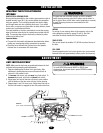
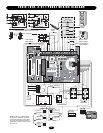
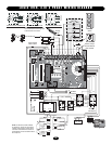
If the door moves in the wrong direction and or the limits move
in the wrong direction, simply move the motor direction jumper
located on the logic board from the factory default setting (STD)
to the (REV) pins. This will change the motor rotation as well as
the functional position of the OPEN and CLOSE limit switch’s.
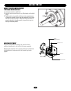
Then relocate the safety limit switch (SLS) only to the opposite
side with the new functional close limit location. Orient the arm
(lever) of the limit switch away from the center. NOTE: The motor
direction change is not available on the DJ and DH models.
EXTERNAL RADIO WIRING CONNECTIONS
On all models a radio terminal bracket marked R1 R2 R3 is
located on the outside of the electrical enclosure. In B2 mode the
operator will then open a fully closed door, close a fully open
door, stop an opening door, and reverse a closing door from the
radio remote. In TS control wiring the operator will only open the
door or reset the timer to close. However, for additional door
control from a 3-button remote, a commercial three-channel radio
receiver (with connections for OPEN/CLOSE/STOP) is
recommended.
NOTE: If an external radio receiver is being used in place of the
built-in receiver, remove or disconnect the coaxial cable from the
logic board.
MOUNTING INSTRUCTIONS
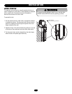
1. Mount WARNING NOTICE beside or below the control station.
2. Mount MAINTENANCE ALERT label to either side of control
station.
3. Mount control station(s) within line of sight of door(s).
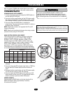
CONTROL WIRING
USE COPPER WIRE ONLY
40-10032B
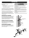
To prevent possible SERIOUS INJURY or DEATH, install
reversing sensors when the 3-button control station is out of
sight of the door or ANY other control (automatic or manual) is
used. Reversing devices are recommended for ALL installations.
WARNING
CAUTION
WARNING
WARNING
OR IN THE AREA NEAR THE OPERATOR MUST
NOT BE PERFORMED UNTIL DISCONNECTING
THE ELECTRICAL POWER AND LOCKING-OUT
THE POWER VIA, THE MAIN DISCONNECT
SWITCH. UPON COMPLETION OF
MAINTENANCE THE AREA MUST BE CLEARED
AND SECURED, AT THAT TIME THE UNIT MAY
BE RETURNED TO SERVICE.
Maintenance
Alert System
TM
If light is Flashing
Rapidly, it is time
for routine door
maintenance.
If light is Flashing
Slowly, followed
by a pause, call for
immediate service.
Service every
cycles/months
4'
Approximate
Control
Station
Optional
Controls
POWER
TIMER
DEFEAT
MAS
4
TS
DIAG
ROG
24V
AC
24V
AC
TIMER
DEFEAT
CMN
MAS
EYES
EDGE
OPEN
CLOSE
STOP
CMN
SBC
11
10
9
14
13
12
8
7
6
5
4
3
2
1
CLOSE
STOP
OPEN
EDGE
EYES
P1
D34
F1
D1 E2
)
AILSAFE
D23
D15
R8
C18
D8
U7
R31
D31
C3
Ø
D7
D6
D5
D4C25
C17
P1
Ø
A
D2
Ø
D21
D13
D14
D28
D17
D19
SBC
24V
AC
24V
AC
TIMER
DEFEAT
CMN
MAS
EYES
EDGE
OPEN
CLOSE
STOP
CMN
SBC
11
10
9
14
13
12
8
7
6
5
4
3
2
1
24 VOLT AC
24 VOLT AC
TIMER DEFEAT
COMMON
MAINTENANCE ALERT SYSTEM
PHOTO EYES (LiftMaster Only)
REVERSE
OPEN
CLOSE
STOP
COMMON
INTERLOCK
INTERLOCK
SINGLE BUTTON CONTROL