


16
PROGRAMMING
DETERMINE AND SET WIRING TYPE
Read the descriptions of the different wiring types to determine
which setting will be correct for each application.
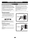
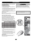
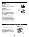
SET THE SELECTOR DIAL TO THE DESIRED WIRING MODE:
NOTE: For failsafe wiring you must also set failsafe switch to
FAILSAFE.
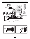
TYPE
C2 Momentary contact to open and stop with constant
pressure to close, open override plus wiring for sensing
device to reverse. Programmable mid stop available with
this wiring type. Compatible with 3-Button Station and
1-Button Station.
B2 Momentary contact to open, close and stop, plus wiring
for sensing device to reverse and auxiliary devices to
open and close with open override. Programmable mid
stop available with this wiring type. Compatible with
3-Button Station, 1-Button Station and 1 & 3-Button
Remote Controls.
D1 Constant pressure to open and close with wiring for
sensing device to stop. Compatible with 2-Button
Station.
E2 Momentary contact to open with override and constant
pressure to close. Release of close button will cause
door to reverse (roll-back feature) plus wiring for
sensing device to reverse. Compatible with 3-Button
Station.
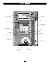
SELECTOR DIAL
FAILSAFE SWITCH
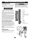
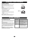
LOGIC CONTROL PUSHBUTTONS OPEN, CLOSE, STOP
Open, Close and Stop buttons are mounted directly on the logic
board. Thus, making it easy to program as well as have door
control at the electrical box. Either the stop control or a jumper
must be wired between terminals 4 and 5 for the on board push
buttons to function.
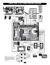
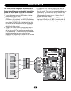
NOTE: Refer to logic board illustration on page 15 for all
component locations. Before programming the logic board, set
the operators open and close limits. LEDs on the logic board are
provided to assist setting the limits. As each limit is activated the
corresponding LED will light up. The abbreviations are Open
Limit Switch (OLS), Close Limit Switch (CLS) and Sensing Limit
Switch (SLS). Refer to page 8 for limit switch adjustment
instructions.