


Preparing the Installation 9
Doc 01-G0674
Rev E
Preparing the Site
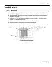
1 Be sure that selected gate location has required clearance for arm movement (and
counterweights on model BG790). Refer to the dimensional drawings, Figure 1 and Figure 2
on page 4.
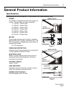
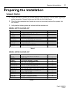
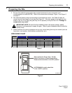
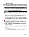
2 Run electrical power to the site according to local electrical codes. See Table 3 below for
correct wire size and length of run (see also Figure 3). If the wire gauge is too high (wire too
small) or the run is too long, the gate may not run properly or may not run at all. Damage to
components may result.
IMPORTANT NOTE: Be sure that the available power is the proper voltage, phase,
frequency, and amperage to supply the gate. Refer to gate nameplate located inside the
service cover.
3 Select locations for control equipment and run any control wiring that may be needed (such as
loop wires, card readers, ticket spitters, pushbuttons, etc.).
WIRE SIZING CHART
SINGLE PHASE THREE PHASE
115VAC 230VAC 230 VAC 460 VAC 575VAC
AWG Maximum Length of Wire Run in Feet
6 700 3,100 4,750 14,225 35,550
8 450 1,925 3,000 8,975 22,425
10 275 1,225 1,900 5,650 14,075
12 175 775 1,175 3,525 8,825
Table 3
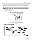
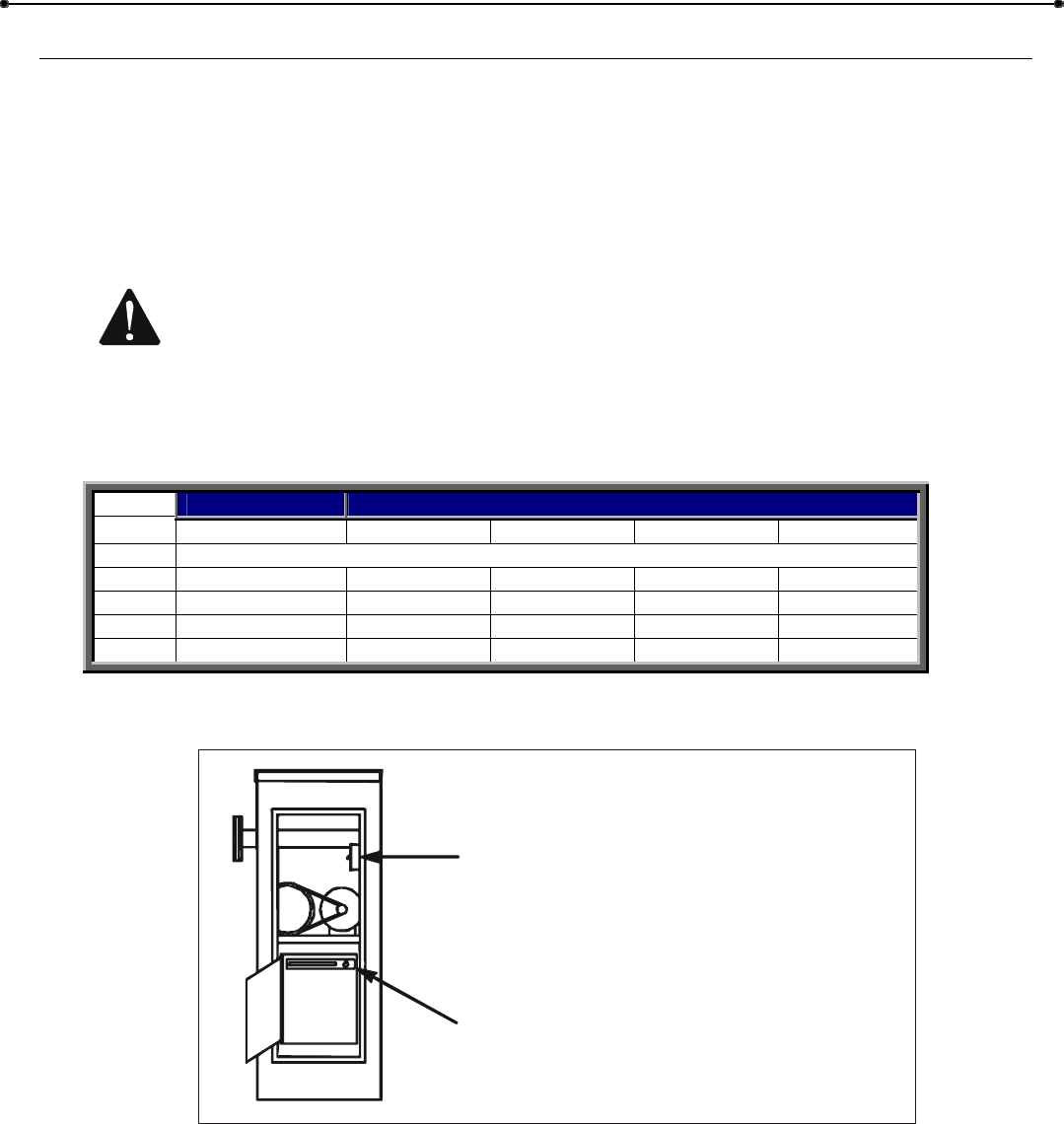
Note: Install Line Power Here. Do Not
Install Line Power in Panel shown below.
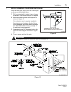
Power switch should be in the OFF position.
AUTO/MANUAL switch should be
in the “AUTO” position.
01-G0674F5
Figure 3