


Installation 13
Doc 01-G0674
Rev E
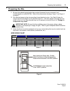
Step 3:
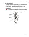
Wiring Connections
Locate the electrical enclosure inside the cabinet. The enclosure (shipped loose) may be removed
from the cabinet to help in the connections described below. When all connections are complete, hang
the enclosure as described in step 7.
WARNING
Consult local electrical codes for permanent wiring requirements at you installation site.
1 Open the cover of the electrical enclosure. Refer to the wiring diagram supplied inside for all
electrical connections.
2 Be sure that power supply is of the correct voltage, phase, frequency, and amperage to supply
operator. Refer to the operator nameplate on electrical cabinet cover.
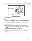
CAUTION
Do not turn on electrical power until you have carefully read the Limit Switch Adjustments
section on page 18. Also, this unit must be properly grounded. A ground screw is supplied in
the switch box for connection of the power supply ground wire. Failure to properly ground
this unit could result in electrical shock and serious injury.
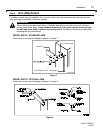
3 Connect power supply wires to the ON/OFF power switch as shown on the operator wiring
diagram and Figure 3 (see page 9). Do Not connect power at control panel (L1, L2, L3).
Route wires away from belt and limit switches.
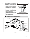
4 A two button control station (OPEN/CLOSE) is provided as standard equipment with every
BG770 and BG790 barrier gate. If you are not using automatic controls to control the gate, the
two button station may be connected as shown on the wiring diagram supplied with the gate to
control the gate manually. However, the AUTO/MANUAL switch should be kept in the "AUTO"
position.
IMPORTANT NOTE: Use 16 gauge wire or larger for all control wiring connections. If the
control wire is too small, damage to the operator components may result.
5 The control station must be mounted in a location adjacent to and within clear sight of the
gate. If you will mount the control station outdoors, replace the standard station supplied with
the operator with a weatherproof station.
6 The BG770 and BG790 barrier gates will interface with almost all types of commonly used
control stations, radio controls, and access control equipment. Refer to the wiring diagram for
connection of these devices.
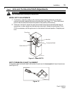
If you are using a loop detector to open and/or hold open and close, mounting space and plug-
in harnesses are provided in the electrical cabinet for installation of optional factory supplied
detectors. You may also use other detectors. Refer to the Optional Accessories section on
page 19.
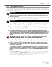
7 When all wiring connections are complete, mount the electrical enclosure to the shelf housing
shelf. MODEL BG770: Hang electrical enclosure on the two screws provided on the front of
the shelf in the housing. MODEL BG790: Hang electrical enclosure on the two screws
provided on the cross angle under shelf in the housing.