


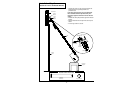
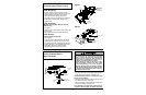
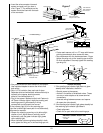
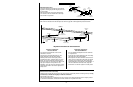
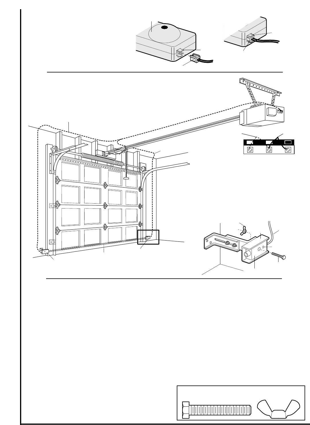
Invisible Light Beam
Protection Area
Sensor
Sensor
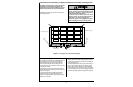
Connect Wire to
Opener Terminals
Bell Wire
Bell Wire
— Finished Ceiling —
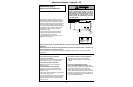
OPENER TERMINAL SCREWS
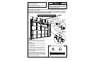
Sensor
Connections
Wall Control
Connections
(dotted line)
1
2 3
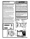
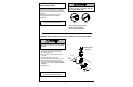
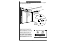
1/4-20x1-1/2"
Hex Bolt
"C" Wrap
Wire
Sensor
Wing Nut
Indicator Light
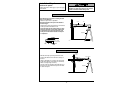
• Run paired wires from both sensors to the opener.
Use insulated staples to secure the wire to wall
and ceiling.
• Strip 1/4" of insulation from each set of wires.
Separate white and white/black wires sufficiently to
connect to the opener terminal screws:
white to 2 and white/black to 3.
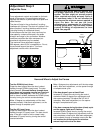
• Plug in the opener. Make sure the Lock Feature is
off
. Green indicator lights in both the sending and
receiving eyes will
glow steadily
if wiring
connections and alignment are correct.
If the indicator light is
off
in the
receiving eye
(and the invisible light beam path is not obstructed),
alignment is required.
• Loosen the receiving eye wing nut to allow slight
rotation of unit. Adjust sensor vertically and/or
horizontally until the green indicator light
glows
with a steady light
.
• When indicator lights are
glowing steadily
in both
units, tighten the wing nut in the receiving eye unit.
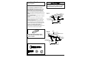
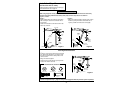
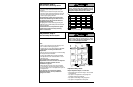
23
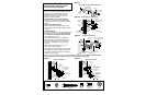
Push connector in
until you hear a click
Tab should be
flush with back
of connector
Wire Connector
White Tab
Safety Sensor
Trouble Shooting
1. If the
sending eye
indicator light does not
glow
steadily
after installation, check for:
• Electric power to the opener.
• A short in the white or white/black wires. These
can occur under staples or at screw terminal
connections.
• Incorrect wiring between sensors and opener.
• An open wire (wire break).
2. If the sending eye indicator light
glows steadily
but
the receiving eye indicator light doesn't:
• Check alignment.
• Check for an open wire to the receiving eye.
1/4-20x1-1/2"
Hex Bolt
Wing Nut
Hardware Shown Actual Size
Figure 7
• Insert the wire connector into each
sensor and push until you hear a
click, Figure 7. The white tab on the
sensor should be flush with the back
of the connector.
• Center each sensor unit in a "C" wrap with lenses
pointing toward each other across the door.
• Secure sensors with the hardware shown. Finger
tighten the wing nut on the
receiving eye
to allow
for final adjustment. Securely tighten the
sending
eye
wing nut.