


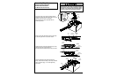
Installation Step 6
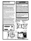
Install the Door Control
18
Children operating or playing with a garage
door opener can injure themselves or others.
The garage door could close and cause
serious injury or death.
Install the Door Control (or any additional push
buttons) out of the reach of children and away
from all moving parts of the door and door
hardware,
but where the garage door is visible.
Do not allow children to operate the push
button(s) or the remote control transmitter(s).
A moving garage door could injure someone
under it.
Activate the opener only when the
door is properly adjusted, you can see it clearly,
and there are no obstructions to door travel.
2-Conductor
Bell Wire
The Chamberlain Group, Inc
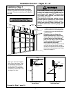
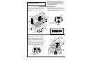
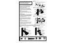
Step 6 Install Lighted Door Control Button
CGI Multifunction/Pushbutton
10/8/91 - 5/2/92 - 5/4/92 - 5/26/92
Lighted
Door
Control
Terminal
Screws
2-Conductor
Bell Wire
WHT
2
RED
1
Door Control
Push Bar
LIGHT
LOCK
WHITE
Multi-Function
Door Control Panel
RED
Light Button
Lock Button
Multi-Function
Door Control Panel
Terminal Screws
2-Conductor
Bell Wire
Lighted
Door Control
Button
1
2
Opener
Terminal
Screws
Antenna
Back Panel
of Opener
KG
KG
1
3
9
7
5
1
3
9
7
5
2 3
1
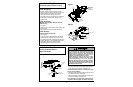
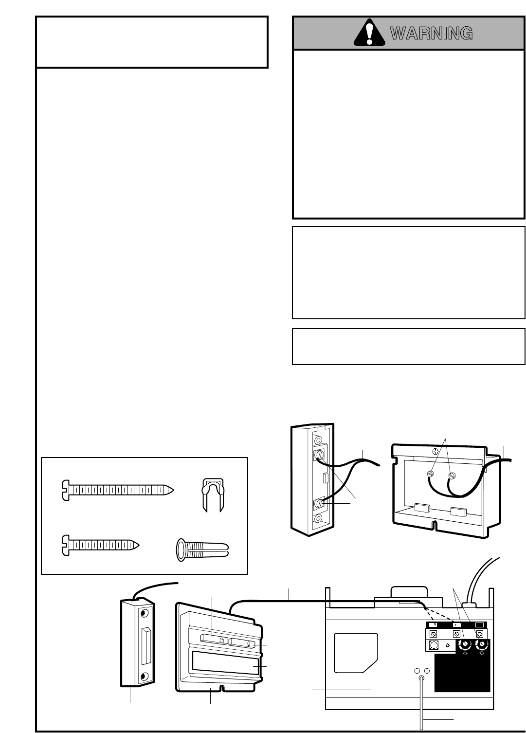
• Strip 1/4" of insulation from one end of the bell
wire; connect the wire to the two screw terminals
on the back of the door control by color: white to 2
and white/red to 1.
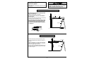
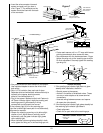
• Locate the door control within sight of the door
at a minimum height of 5 feet where small
children cannot reach, and away from all
moving parts of the door and door hardware.
Fasten the Lighted Door Control Button securely
with 6ABx1-1/2" screws. The Multi-Function Door
Control Panel uses 6ABx1" screws. If installing
into drywall, drill 5/32" holes and use the anchors
provided.
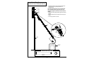
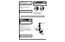
• Run the bell wire up the wall and across the ceiling
to the opener. Use insulated staples to secure the
wire in several places. Be careful not to pierce the
wire with a staple, thereby resulting in a short.
• Receiver terminals screws and the antenna are
located on the back panel of the opener. Position
the antenna wire as shown.
• Then connect the bell wire to the opener terminal
screws: white to 2 and white/red to 1.
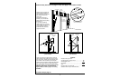
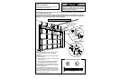
• Remember to affix the User Safety Instruction
label to the wall near the Door Control, and the
Maintenance Instruction label in a prominent
location on the inside of the garage door.
Page 32 explains how to operate the opener using
the Door Controls and the Lock and Light features
available on the Multi-Function Door Control Panel.
If the label adhesive will not adhere to your garage
wall surface (or becomes loose with time) use tacks
to secure the label alongside the control button.
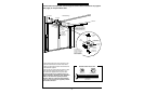
Do NOT connect the power and operate the
opener at this time.
The trolley will travel to the
full
open
position but will not return to the
close
position until the sensor beam is
connected and properly aligned.
See Safety Reversing Sensor instructions
beginning on page 21.
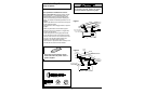
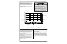
Dry Wall Anchors
Insulated
Staples
6ABx1" Screw
Multi-Function Door Control Panel
6ABx1-1/2" Screw
Lighted Door Control Button
Hardware Shown Actual Size
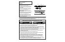
Outside Keylock Accessory Connections
To opener terminal screws: white to 2; white/red to 1
WARNING
Models 1260, 1260-166,
1260-266, 1250 &
1250-266
Models 1256, 1255,
1255-166, 1255-266,
1246, 1245, 1245-266
& 1240