


15
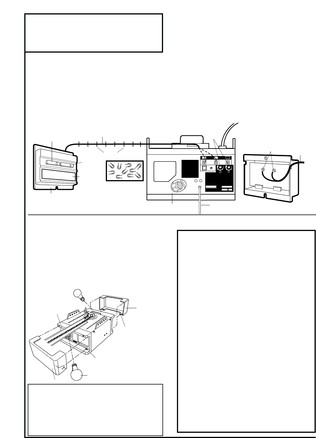
Install Multi-Function Door
Control Panel
(Model 5000E Only)
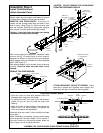
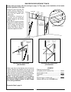
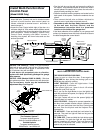
• Remove about 6mm of insulation from both ends of 2-
strand bell wire. Connect one end to terminal screws
on back of multi-function door control panel as
follows: white/red to terminal screw 1 and white to
terminal screw 2.
• Locate the Door Control within sight of the door at a
minimum height of 3.5m where small children cannot
reach, and away from all moving parts of the door and
door hardware. Fasten the Multi-Function Door
Control Panel securely with 6ABx1" screws. If
installing into drywall, drill 4mm holes and use the
anchors provided.
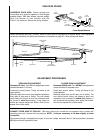
• Run the bell wire up the wall and across the ceiling to
the opener. Use insulated staples to secure the wire in
several places. Be careful not to pierce the wire with a
staple, thereby resulting in a short.
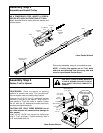
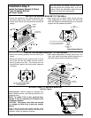
• Receiver terminals and the antenna are located on the
back panel of the opener. Position the antenna wire as
shown.
• Then connect the bell wire as follows: white/red to
terminal screw 1 and white to terminal screw 2.
• Remember to affix the User Safety Instruction label
to the wall near the Door Control, and the
Maintenance Instruction label in a prominent
location on the inside of the garage door.
If the label adhesive will not adhere to your garage wall
surface (or becomes loose with time) use tacks to secure
the label alongside the control button.
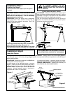
OPERATION OF THE
MULTI-FUNCION DOOR CONTROL PANEL
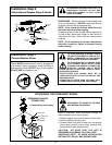
THE DOOR CONTROL PUSH BAR:
Press to open or close the door. Press again to
REVERSE the door during the closing cycle or to
STOP the door while it's opening.
LIGHT FEATURE: Press the Light button. If the
opener light is off, it will turn on.
If the opener light is on, (even in the 4-1/2 minute
automatic cycle) it will turn off.
But if you use the Light Button to turn the light(s) on
and then activate the opener, the light(s) will turn off
after 4-1/2 minutes.
The Light Feature will not turn the opener light(s) off
when the door is in motion.
LOCK FEATURE: Designed to prevent operation of
the door from portable remote controls. However, the
door will open and close from the Door Control push
bar and from the Keylock and the Keyless Entry
Accessories.
TO ACTIVATE: Press and hold the Lock button for 2
seconds. The push bar light will flash as long as the
Lock feature is on.
TO TURN OFF: Press and hold the Lock button again
for 2 seconds. The push bar light will stop flashing.
Normal operation will resume. The Lock feature will
also turn off whenever the "Smart" button on the
opener end panel is activated.
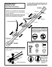
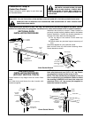
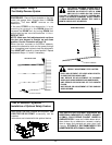
INSTALL THE LIGHT(S): Install a 75 watt maximum
light bulb in each socket. Light will turn ON and remain
lit for 4-1/2 minutes when power is connected. After
4-1/2 minutes, they will turn OFF.
If bulb burns out prematurely due to vibration,
replace with bulb specifically packaged for garage
door openers.
INSTALL LENS (Models 5000E & 4000E): Side lens
into guides as shown. Snap bottom tabs into lens slots.
For convenience, lenses may be installed after
adjustment Step 3 on Page 22.
Staples
2-Strand Bell Wire
Door Control
Push Bar
L
IG
H
T
L
O
C
K
RED
1
Multi-Function
Door Control Panel
WHITE
2
Light
Button
Lock
Button
Multi-Function
Door Control Panel
Terminal Screws
2-Strand
Bell Wire
Opener
Terminal
Screws
Antenna
Back Panel of Opener
KG
KG
M.D.C. CERT. NO.
1
3
9
7
5
132C2105-1
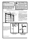
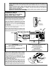
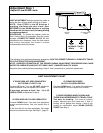
WARNING: To reduce the risk of severe injury
or death by entrapment, when adjusting either
the force or limits of travel controls ensure that
the door reverses on a 1 inch object (or a 2 x 4
board laid flat). See instructions for proper
adjustment procedure.
This device complies
with FCC Rules Part
15. Operation of this
device is subject to the
following conditions:
1. This device may
not cause harmful
interference. 2. This
device must accept
any interference
that may be received,
including interference
that may cause
undesired operation.
PART NO: Nº DE PIÈCE:
D.O.C. CERT. NO.
DATE:
Sears Roebuck & Co.
Sears Canada Inc., Toronto
Assembled in Mexico - Assemblé du Mexique
PAT. #RE29,525; 4,750,201; 4,806,930 Other Patents Pending.
AVERTISSEMENT: Pour réduire les risques de
blessures mortelles par happement, après tout
réglage de la force de déclenchement ou des
seuils de fin de course s'assurer que le sens de
la course s'inverse lorsque la porte entre en
contact avec un object de 13 mm (1 po) de
hauteur (ou un madrier de 2 x 4 de section, à
plat) posé sur le sol. Effectuer les reglages
selon les procédures décrites dans la notice.
1
3
9
7
5
2 3
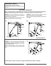
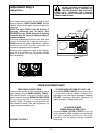
TO PROGRAM RECEIVER CODE
FOR EACH REMOTE CONTROL
1. Press and HOLD remote control
transmitter push button.
2. Press receiver code button. The opener
light will flash once.
3. Release transmnitter button. Opener
has learned code.
TO ERASE ALL RECEIVER CODES
1. Press and HOLD receiver code button.
Green indicator light alongside will turn
ON.
2. When light turns OFF (about 6
seconds) ALL codes are erased from
opener memory.
1
Lens
Guide
Lens
Tab
Lens
Slot
75 Watt Max.
Light Bulb
(Model 5000E Only)
Lens
WIRING INSTRUCTIONS FOR ACCESSORIES
The Protector System™
To opener terminal screws:
White to 2 and White/Black to 3
Outside Keylock:
To opener terminal screws:
White/Red to 1 and White to 2