


13
Installation Step 3
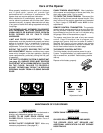
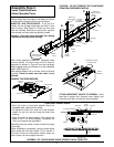
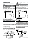
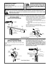
Position the Opener
Follow instructions which apply to your door type as
illustrated.
Installation Step 4
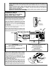
Hang the Opener
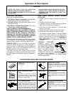
TO PREVENT DAMAGE TO ALL
LIGHT-WEIGHT DOORS AND DOORS WITH
WINDOWS, DO NOT REST THE OPENER ON
THE DOOR.
WARNING
CAUTION
WARNING
WARNING
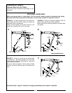
SECTIONAL DOOR & 1-PIECE DOOR WITH TRACK
1-PIECE DOOR WITHOUT TRACK
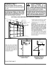
NOTE: A 25mm board is convenient for setting an
ideal door-to-T-rail distance. It is not necessary
when headroom is insufficient.
PROCEDURE: Raise the opener onto a stepladder.
Open garage door. Place a 25mm board on the top
section of door near centerline as shown. Rest T-rail
on 25mm board as shown.
PROCEDURE: Measure the distance from floor to top of
door (in fully open position and parallel to the floor). Using a
stepladder as a support, raise opener to the same distance
from the floor (it will have a slight angle as shown).
The top of the door should be level with the top of
opener. For maximum efficiency, do not position opener
more than 5cm above this point.
T-rail
25mm
Board
Door
Stepladder
Top of Opener
Header
Bracket
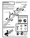
THE OPENER MUST BE SECURELY FASTENED
TO A STRUCTURAL SUPPORT OF THE GARAGE.
Two representative installations are shown. Yours may be different. Hanging brackets should be angled (Figure 1)
to provide rigid support. On finished ceilings (Figure 2) attach a sturdy metal bracket (not supplied) to structural supports
before installing opener.
PROCEDURE: Measure the distance from EACH side
of the opener to structural support.
Cut both pieces of the hanging bracket to required
lengths. Flatten one end of each bracket and bend or
twist to fit the fastening angles. Do not bend at the
brackets holes. Drill 5mm pilot holes in the structural
supports. Attach flattened ends of brackets to
suppports with 5/16"x1-7/8" lag screws.
Lift opener and fasten to hanging bracket as shown.
Check to make sure T-rail is centered over door.
REMOVE 25MM BOARD. Operate door manually. If
door hits the rail, raise header bracket.
Measure
Distance
Lag Screws
5/16"x1-7/8"
Structural
Supports
5/16"-18x7/8" Screw
5/16" Lock Washer
5/16"-18 Nut
Bracket
(Not Supplied)
Lag Screws
5/16"x1-7/8"
(Not Supplied)
5/16"-18x7/8" Screw
5/16" Lock Washer
5/16"-18 Nut
– FINISHED CEILING –
13mm Socket Wrench
Figure 1
Figure 2
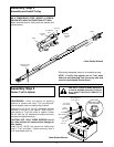
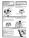
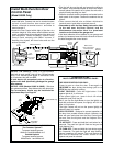
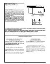
If the top panel hits the trolley when you raise the
door, pull down the trolley release arm to
disconnect the inner and outer sections. The trolley
can remain disconnected until Step 9 is completed.
Trolley
Trolley
Release Arm