


8
10000801
Vermont Castings, Majestic Products RHEDV Direct Vent Insert
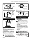
4. The chimney must be clean and in good working
order and constructed of noncombustible materials.
5. Make sure that all chimney cleanouts fit properly so
air cannot leak into the chimney.
6. Install the appliance without trim frame and make all
gas fittings and electrical connections.
7. Install the decorative trim frame. Please refer to the
Frame Assembly instructions.
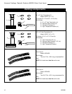
Liner Installation - Fig. 9
Installer must attach red warning plate
with screws supplied with the gas fire-
place insert to the inside of the firebox of
the fireplace into which the gas fireplace
insert is installed.
Cutting any sheet metal parts of the
fireplace, in which the gas fireplace insert
is to be installed, is prohibited.
If the factory-built fireplace has no gas
access hole(s) provided, an access hole
of 1.5 inch (37.5mm) or less may be
drilled through the lower sides or bottom
of the firebox in a proper workmanship
like manner. This access hole must be p
lugged with a noncombustible insulation
after the gas supply line has been in-
stalled.
WARNING
Some factory-built fireplaces have air passages
on face of fireplace for zero clearance capabilities.
All trim kits are designed so as to allow airflow to
these passages. Under no circumstances should
these passages be blocked.
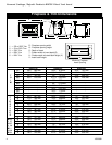
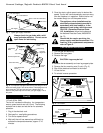
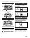
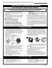
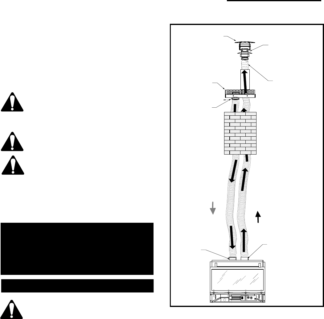
The collar extending down from the termina-
tion base is the air intake connector. Be sure
the flex vent, which is connected to this
collar, is also connected to the labelled air
intake flue collar on the fireplace. Make sure
the Flex vent is attached on the correct collar
and cap for exhaust as well.
Slide the insulation provided in the termination kit over
the two (2) 3" flex liners, (to be attached to the 3" Flue
collar and cap of the termination). Feed one 3" flex vent
from the bottom of the termination up through the 4"
sleeve. Apply hi-temp sealant on the rain cap collar
and slide the flex vent over the end of the rain cap
collar fastening with the clamp provided. Slide the flex
liner back down the 4" sleeve until 4" cap slides over
the sleeve. Attach cap to the sleeve with four (4) screws
supplied. Apply hi-temp sealant over the air intake
collar and attach intake flex vent in the same method.
Feed the two flex liners down the chimney through the
damper opening. Tighten termination to the chimney
using the screws provided.
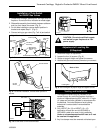
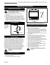
In case the fireplace opening is only minimum height
21" (533mm) and access from the front is not possible,
then follow the instructions below.
1. Remove flue collar plate assembly. Unbolt the top
fastener plate and move it to the back first before
sliding the flue collar plate out from the top of the
unit. (Fig. 10)
2. Apply a bead of hi-temp sealant on the end of the
collar before attaching the liner to the flue collar.
Fasten it with two clamps then adjust fastener plate
all the way to the back before sliding flue gas plate
back onto the unit. (Fig. 11 and Fig. 12)
Flue gas exits
through the vent
termination rain
cap
1) Attach flexible pipe
to rain cap
2) Secure with clamp
3) Attach raincap to
vent termination using
three screws
Pull flexible pipe
through vent
termination
Outside combustion
air enters through the
lower level of the vent
termination
Secure with
clamp and
three screws
Air Intake
Exhaust
Air intake collar
with label
secured with
clamp and three
screws
Exhaust collar secured
with clamp and three
screws
FP1280
NOTE
Minimum Vent Height -
12 feet
Maximum Vent Height -
35 feet
Fig. 9 Liner installation.