


31
10000801
Vermont Castings, Majestic Products RHEDV Direct Vent Insert
B4 HEBTKP, HESBTKP, HECBTK, HECBTKMB & HEBTA Trims
For use with RHEDV32
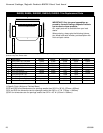
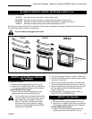
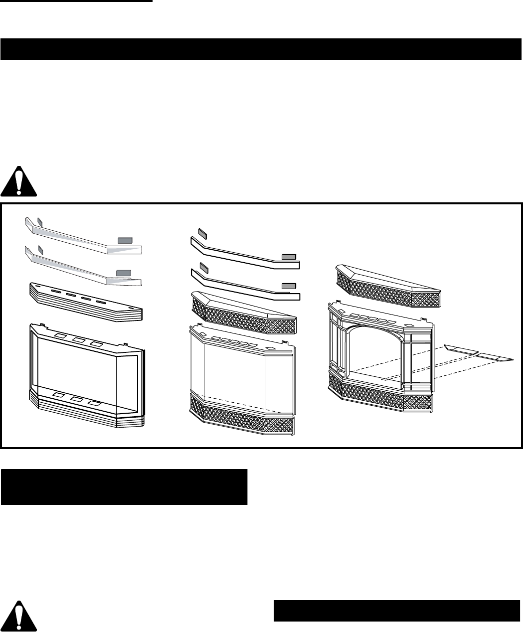
HECBTK Cast bay window and grilles in classic black trim kit
HECBKMB Cast bay window and grilles in midnight black porcelain enamel trim kit
HESBTKP Steel bay window with polished brass and cast grilles in classic black trim kit
HEBTKP Steel bay window and bay louvres with polished brass trim kit
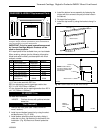
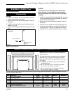
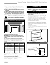
Install the bay window after all other installation work has been completed, thoroughly checked and tested for opera-
tion, leaks and proper installation requirements.
Do not remove existing glass with frame
Fig. 46 Optional bay front windows available for use on the RHEDV32.
HECBTKP, HECBTKMB and HESBTKP
Trim Assembly
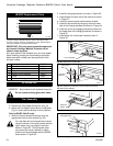
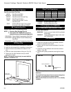
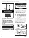
1. Reposition controls.
a. Remove the Fan Speed Control Box (Fig. 47)
b. Attach the Fan Speed Control Box to the Bracket
(Fig. 48) and install the Bracket into the Cabinet.
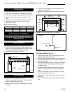
Only for RN/RP VALVE units:
c. Install the Control Knobs Extensions onto the
appropriate Control Valve Knobs (Fig. 49)
On units fitted with a Honeywell brand control
valve the location of the control knobs and the
ignitor button may vary slightly from those
shown in Figure 49. The Honeywell exten-
sion pieces are visually different in design
and are not interchangeable with the RN/RP
knobs shown in Figure 49.
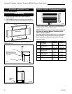
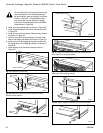
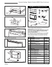
2. Install the hanging brackets, as shown in Figure 50.
3. Install the two ceramic pieces inside the bay window,
as shown in Figure 46.
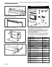
4. Install the bay window by hanging it onto the lower
tabs of the hanging brackets, as shown in Figure 51.
5. Install the upper grille by engaging the oblong holes
with the upper tabs of the hanging brackets, as
shown in Figure 52.
6. Install brass trim to the steel frame as shown in
Figure 53. (Only for HESBTKP trim).
HEBTKP Trim Assembly
1. Reposition controls.
a. Remove the Fan Speed Control Box (Fig. 47)
b. Attach the Fan Speed Control Box to the Bracket
(Fig. 48) and install the Bracket into the Cabinet.
Only for RN/RP VALVE units:
c. Install the Control Knobs Extensions onto the
appropriate Control Valve Knobs. (Fig. 49)
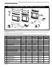
HEBTKP
HESBTKP
HECBTK &
HECBTKMB