


6
10000801
Vermont Castings, Majestic Products RHEDV Direct Vent Insert
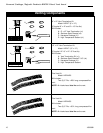
Always check for gas leaks with a mild
soap and water solution. Do not use an
open flame for leak testing.
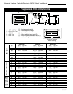
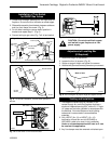
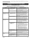
it
HI
LO
OFF
PILOT
Thermostat
Bulb
Brass
Plug
Gas Inlet
Manifold Gas
Outlet
Brass Plug
Pressure
Regulator
Control
Knob
Thermocouple Inlet
Pilot Tube Entry
Pilot Adjustment
Screw
Control Knob
Minimum Rate Screw
(Nonadjustable)
HV118
Fig. 2 On fireplaces equipped with the Eurosit 630 gas valve,
there are brass plugs in two of the holes. These plugs are not
to be removed. The gas inlet hole has a plastic cap in it.
Remove the plastic cap and connect your gas supply line at
this point.
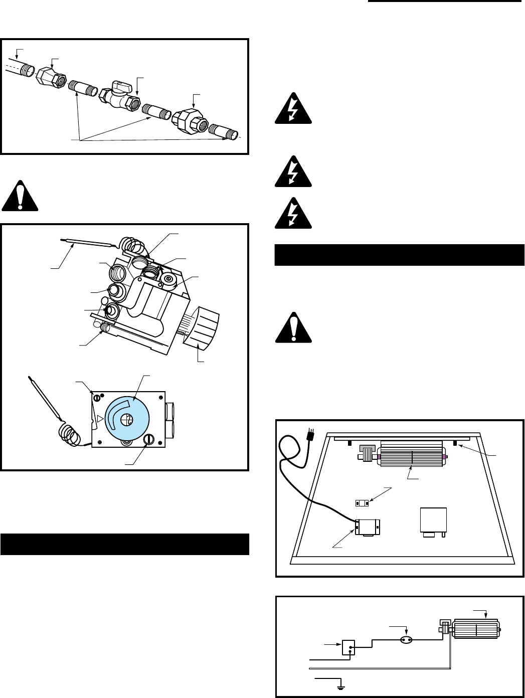
115 volt, 60 Hz. 56W
The fan kit includes the following: fan, temperature
sensor, speed control and a 6 ft. cord. The following
explains how to start and set the fan for automatic
operation.
1. Plug in the electrical cord.
2. Start gas fire - see lighting procedures.
3. Turn on fan speed control.
4. Wait until the unit has warmed up sufficiently to
activate the termperature sensor, approx. 5-10
minutes.
Fan Kit
5. Once fan starts, adjust speed control to desired fan
speed. The fan will now automatically come on every
time the fireplace is in operation. Should the fan not
be needed simply turn off the speed control.
The appliance, when installed must be
electrically connected and grounded in
accordance with local codes or, in the
absence of local codes, with the current
CSA C22.1 Canadian Electrical Code.
U.S. Installations, follow local codes and
the National Electrical Code, ANSI/NFPA
No. 70.
Should this fan require servicing, the
power supply must be disconnected. For
rewiring of any replacement components
refer to Figure 4.
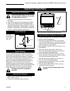
Fan Removal Instructions
1. Turn off gas and electricity.
2. Remove the front glass.
3. Remove the logs.
CAUTION: Logs may be hot!
4. Remove burner assembly and rear log support plate.
5. Remove the fan mounting nuts (2 nuts). (Fig. 3)
6. Slip off the electrical connector at the motor.
7. Lift out the fan.
8. To reinstall reverse procedure.
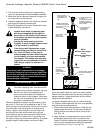
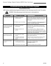
Thermal Sensor is
Attached to Burner
Base
Fan is Installed at
the Back of the
Air Intake Box
Fan Speed Control/Junction Box
Screw
Stud
Screw Stud
FP1252
Fig. 3 Fan location.
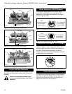
Fan
Temperature Sensor
Speed
Control
Black
White
Ground
FP394
Fig. 4 Wiring diagram.
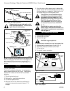
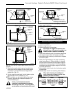
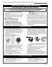
1/2" Gas Supply
1/2" x 3/8" Reducer
3/8" x 3/8" Shut Off Valve
3/8" Union
3/8" Nipple
FP1278
Fig. 1 Typical gas supply installation.