


19
Irving Oil
10004000
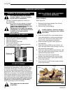
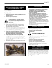
1. It is important to keep the burner and the burner
compartment clean. This must be done
periodically, at least once per season (See
Cleaning Procedure).
2. Clean the brass trim using a soft clean cloth,
slightly dampened with lemon oil and buff with a
soft clean cloth. Do NOT use brass polish or
household cleaners as these products will damage
the brass trim. Lemon oil can be obtained at
supermarkets or hardware stores.
3. The FK24 Fan requires periodic cleaning. Check
the fan and the area around the fan assembly and
wipe or vacuum at least once per month during the
operating season.
4. Contact your local representative to arrange an
annual service program
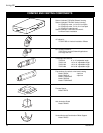
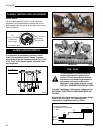
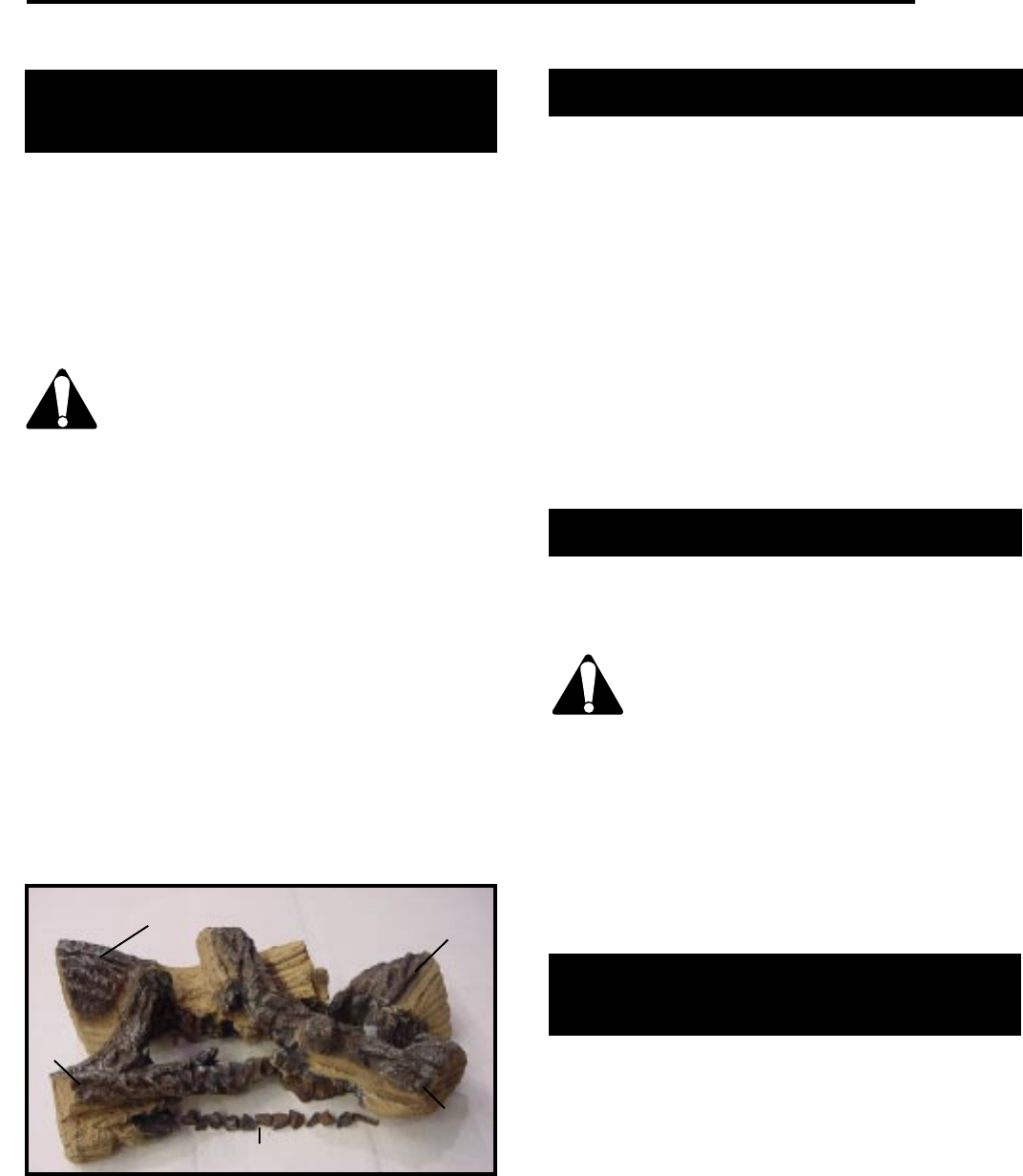
INSTALLATION OF LOGS & BURNER
LAVA ROCK MATERIAL (Cont.)
Model: IRFSDV24
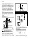
Refer Figure 33.
1. Remove window frame assembly (See Window Frame
Assembly section).
2. Remove logs from packaging.
As with all plastic - these are not toys
and should be kept away from children
and infants.
3. Place rear left log (KR15) with one end onto the
left rear bracket while the rest of the log sets on
the center of the rear log support.
4. Fit the rear right log (KR16) onto the right side of
the rear log support. Ensure the log’s bottom holes
are located on the two studs of the support.
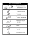
5. Place front left log (KR13) onto the left cut out of
the rear log while the front left end of this log will
set against the back wall of the front grate.
6. Place the front right log (KR14) in position by
resting the holes under one end of this log located
over the knob on the rear left log while the other
end of the log sets against the right end of the front
grate (See Fig. 33).
7. Place burner lava rock over the front area of the burner.
Fig. 33
Burner Lava Rock
KR14
KR13
KR15
KR16
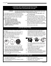
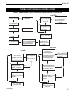
MAINTENANCE
1. Turn off pilot light at gas valve.
2. Remove window frame assembly.
3. Remove logs.
CAUTION: LOGS MAY BE HOT
4. Vacuum burner compartment especially around
orifice/primary air openings.
5. Reinstall logs.
6. Check pilot and main burner operation.
7. Reinstall window frame assembly.
8. Recheck pilot and main burner operation.
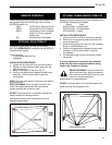
9. Check visually the flame pattern and compare
with Figs. 34, 35, & 36.
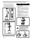
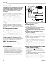
CLEANING PROCEDURE
FLAME & TEMPERATURE
ADJUSTMENT RFN/RFP
All adjustments on units fitted with the Honeywell
Radio Frequency control valve are performed with
the remote transmitter. See instructions packaged
with the transmitter, or page 23 in this manual for
operating details.