


10
Irving Oil
10004000
VERTICAL SIDEWALL APPLICATIONS
Since it is very important that the venting system
maintain its balance between the combustion air intake
and the flue gas exhaust, certain limitations as to vent
configurations apply and must be strictly adhered to.
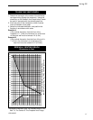
The graph, on page 11, showing the relationship
between vertical and horizontal side wall venting will
help to determine the various lengths allowable.
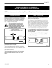
Minimum clearance between vent pipes and
combustible materials is one 1” (25mm) on top, bottom
and sides unless otherwise noted.
When the vent termination exits through
foundations less than 20” below siding outcrop,
the vent pipe must flush up with the siding.
It is always best to locate the fireplace in such a
way that minimizes the number of offsets and
horizontal vent length.
The horizontal vent run refers to the total length of
vent pipe from the flue collar of the fireplace to the
face of the outer wall.
Horizontal plane means no vertical rise exists on
this portion of the vent assembly.
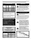
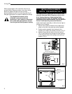
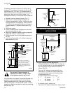
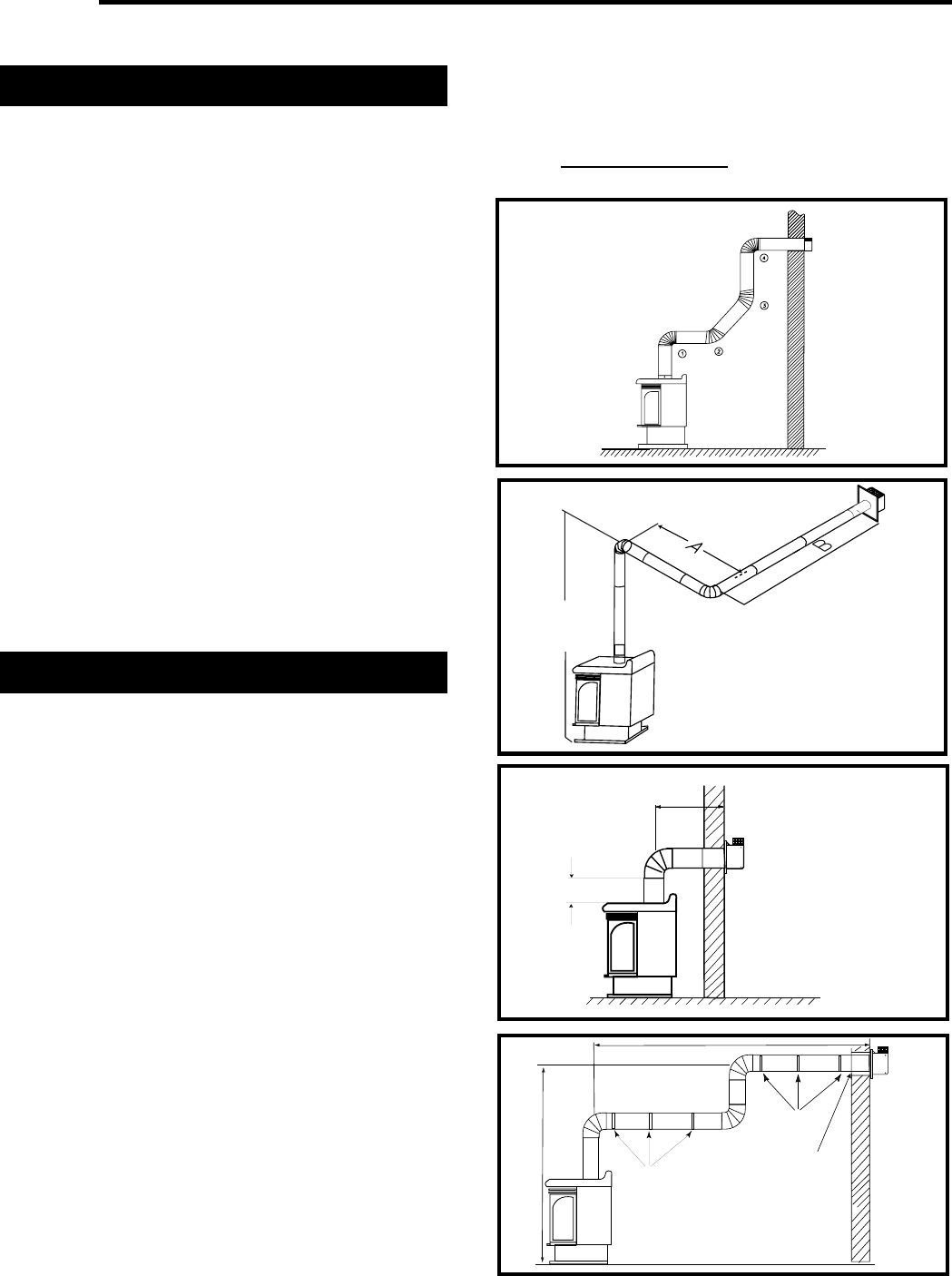
VERTICAL SIDEWALL INSTALLATIONS
• The maximum number of 90° elbows per side wall
installations is three (3).
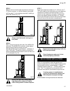
• For IRFSDV24 and IRFSDV34 models the
maximum horizontal run off a minimum 12” vertical
rise is 3’ (see Fig. 15).
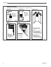
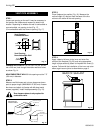
• If a 90˚ elbow is used in the horizontal vent run
(level height maintained) the maximum horizontal vent
length is reduced by 36 inches, (Fig. 14). This does not
apply if the 90˚ elbows are used to increase or redirect
a vertical rise (Fig. 16).
Example: According to the chart the maximum
horizontal vent length is 20’ and if a 90˚ elbow
is required in the horizontal vent it must be
reduced to 17’.
In Fig. 14, Dimension A plus B must not be
greater than 17’ (5.2m).
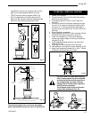
• The maximum number of 45° elbows permitted per
side wall installation is two (2). These elbows can be
installed in either the vertical or horizontal run.
• For each 45° elbow installed in the horizontal run,
the length of the horizontal run MUST be reduced by
18” (45cm). This does not apply if the 45° elbows are
installed on the vertical part of the vent system.
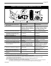
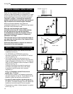
• The maximum number of elbow degrees in a system
is 270° (Fig. 13).
Example: In Figure 13
Elbow 1 = 90°
Elbow 2 = 45°
Elbow 3 = 45°
Elbow 4 = 90°
Total angular variation = 270°
Fig. 14
7.5 ft.
2286mm
A + B = 17 ft.
Fig. 16
20 FT
(610cm)
7.5FT (2286m)
PIPE STRAPS
EVERY 3'
(92cm)
PIPE STRAPS
EVERY 3'
(92cm)
FIRESTOP/ZERO
CLEARANCE SLEEVE
Fig. 13
Fig. 15
3 FT
(92cm)
x
IRFSDV24
IRFSDV24
x = 12”