


9
10002428
Vermont Castings, Majestic Products DVRT36/39/43
The fireplace, when installed, must be
electrically connected and grounded in
accordance with local codes; or, in the
absence of local codes, with the current
CSA C22.1 Canadian Electrical Code
For USA installations, follow the local
codes and the national electrical code
ANSI/NFPA No. 70.
It is strongly suggested that a licensed
electrician perform the wiring of the
EB-1 Electrical Junction Box.
Ensure that the power to the supply
line has been disconnected before
commencing this procedure.
The EB-1 Electrical junction box is fitted with this
model to provide for easy installation of an optional fan
kit.
To connect the EB-1 box to the house electrical supply
follow the steps below:
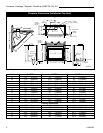
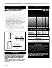
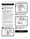
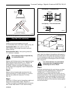
1. Unscrew the retaining screw from the EB-1 base
plate (Fig. 9), and remove the EB-1 assembly from
the fireplace.
2. Remove the front cover of the EB-1 box.
3 Remove the plug socket assembly from the EB-1
box.
4. Feed the supply line in from the outside through the
cable clamp. (Fig. 9)
5. Connect black wire of the power supply line to the
brass screw (polarized) of the socket assembly.
6. Connect the white wire of the power line to the
chrome screw of the socket assembly.
7. Connect the ground wire of the supply line to the
green screw of the socket assembly.
8. Refit the socket assembly back into the electrical
box and replace the cover plate. Secure the cable
with the clamp on the outside of the unit to prevent
strain on the connections.
EB-1 Electrical Box
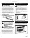
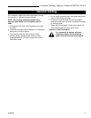
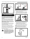
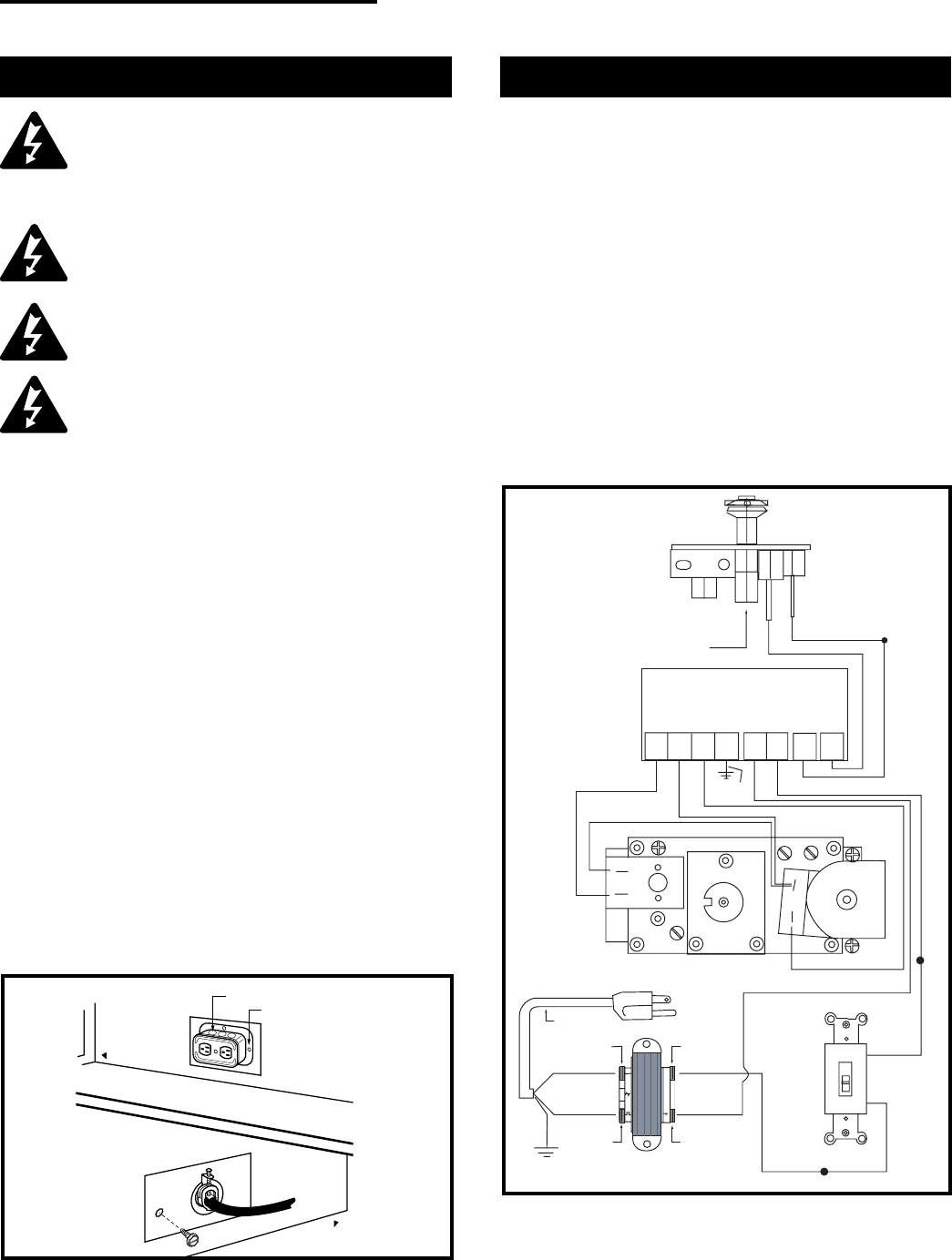
This appliance may be fitted with a Honeywell ignition
module.
Installation of the remote on/off starter switch on
electronic ignition units:
1. Thread the wiring through the holes on the side
panels of the appliance. Take care not to cut the
wire or insulation on metal edges. Route the wire to
a conveniently located receptacle box.
2. Attach the wire to the ON/OFF switch and install the
switch into the receptacle box. (Fig. 10)
3. Connect the White wire from the wall switch to the
Black wire from the transformer, using an approved
wire nut. Connect the Black wire from the wall
switch to the Black wire running from the #6 position
of the ignition module, also using an approved wire
nut.
Electronic Gas Control Valve
PILOT
HONEYWELL IGNITION MODULE
ORANGE
BLUE
BLACK
WHITE
NOVA SIT 822 VALVE
HI
LO
POWER CORD
W/FEMALE SPADE
120 VAC RTN
WHITE
GREEN
BLACK
120 VAC HOT
BLACK
YELLOW
24 VAC RET
40VA TRANSFORMER
24 VAC HOT
BLACK
WHITE
WALL SWITCH
WHITE
OFF
1 2 3 5 6 8 9
MV MV/VP PV GRD 24V SENSE SPARK
24V
ORANGE
RED
GREEN
BLACK
Fig. 10 Honeywell ignition module.
FP1225
Front of Unit
Front of Unit
FP580
Fig. 9 EB-1 receptacle.
Electrical Box
Retaining Screw
Inside
Outside