


21
10002428
Vermont Castings, Majestic Products DVRT36/39/43
Gravity Ducting System
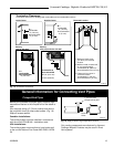
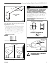
Do not discharge directly into a wall
or inside an enclosure.
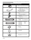
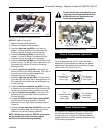
3. Materials needed for the gravity ducting installation:
• (2) 5” dia. duct to grille connector boots
• (2) Wall Outlet grilles
• 5” dia. rigid (“C” vent) or 5” dia. flexible metal
ducting
• 5” dia. elbows (maximum of 3 per run)
4. Remove the gravity duct plugs from the top of the
DVRT43 by taking out the two (2) screws around the
perimeter of each plug, then removing the plugs
from the fireplace.
NOTE: Do not remove the center screw from
the plugs.
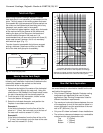
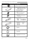
5. Install 5” rigid (C-Vent) or flexible metal ducting on
the DVRT43 and run the ducting, observing the
limitations shown in the graph. Be aware that flexible
ducting is more restrictive to air flow than rigid
ducting.
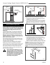
6. Secure all joints with three (3) sheet metal screws.
Seal all joints with foil-faced aluminium tape to
prevent heat loss and maintain maximum air flow.
7. Ensure the following clearances are maintained
when installing the DVRT43 Gravity Ducting System.
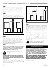
The Gravity Ducting System is only
applicable if installing the DVRT43 Direct
Vent Fireplace.
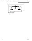
Installation of the DVRT43 fireplace provides an
opportunity to heat either rooms on an upper level or
adjacent rooms on the same level without the use of a
blower. However, with the internal blower installed, there
will be some increase in warm air movement to rooms
serviced by the gravity duct. (Fig. 39 and Fig. 40)
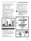
1. Plan the gravity duct run first. Use the following
graph (Fig. 39) to ensure that the installation meets
the recommendations. There is a maximum number
of three (3) elbows in a run, however, the run must
never go in a downward direction, as this can trap
heat in the gravity vent system. Be aware when
designing the ducting system that elbows will restrict
airflow. Minimize the use of elbows in any
installation.
2. It is recommended that the gravity ducting system
be installed so that the grilles exit at the same
vertical level. If the gravity venting system is
installed so the ducting exits at different levels, a
chimney effect may occur, resulting in uneven heat
distribution.
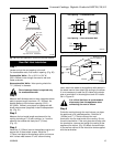
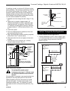
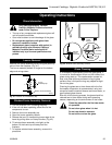
Min.
2’ (610 mm)
FP1189
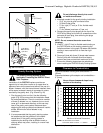
Fig. 37 Minimum termination to roof clearance.
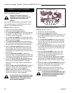
(3) #5 Sheet
Metal Screws
per Joint
Sealant
Storm
Collar
(3) #5
Sheet Metal
Screws per
Joint
Sealant
Storm
Collar
TWL101a
Fig. 38 Roof flashing.
Clearance between ducting and combustibles = 1”
(25mm)
Clearance between grille adapter and combustibles =
0” (0mm)
Never allow a downward slope in any
section of the ducting.
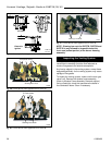
Clearance to Combustibles
2
3
4
5
6
7
8
9
10
56 7 8 91011
12
13 14 15
Vertical Height of Vent from Top of Fireplace
Maximum Horizontal Dimensions
NOTE: All dimensions are in FEET.
Conversion factor to metric: 1’ = 305mm
FP1190
Fig. 39 Gravity vent diagram.