


44
Vermont Castings, Majestic Products DVRT36/39/43
10002428
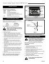
Remote Controls
Optional remote control units are available to control
different functions of the appliance.
Model Function(s) Controlled
MRC1 On/Off
MRC2 On/Off and Temperature
MRC3 On/Off and Temperature control
with digital display and programmable 24-
hour clock
IMT Wall-mounted Thermostat Control
Ceramic Refractory Panels
Ceramic refractory panels are available to line the
firebox area. The ceramic lining kit for the DVRT43 is
supplied standard with the appliance.
Unit Kit Model
DVRT36 CR KIT DVT36
DVRT39 CR KIT DVT39
For installation, refer to Figures 59 and 60.
Take care when handling the refractory
panels, as they are fragile until secured
in place and supported.
Bay window kits are available for the DVRT36 and
DVRT39 model fireplaces.
Installation
1. Remove the existing louvre assembly bottom
complete with the hinges.
2. Remove the louvre assembly top.
3. Assemble the bay window kit according to the
instructions supplied with the kit.
4. Place the two pieces of ceramic refractory along the
base of the bay window. (Fig. 62)
5. Hang the bay window assembly over the existing
window frame assembly.
6. Reinstall the upper louvre assembly.
Do not remove the existing window
frame assembly.
Decorative Bay Window
When fitting the bay window kits the
original front frame/glass assembly must
remain in place. The bay window kit is
fitted over the existing front glass.
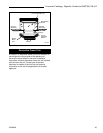
1. Remove the window frame assembly.
2. Remove the logs.
3. Place the lower supports for the side refractory
panels on the base of the firebox. Place each
support so that the slotted hole fits over the forward
screw head along the edge of the base.
4. Lay the angular base panels in place on the floor of
the firebox on either side of the burner housing
assembly.
5. Loosely attach the top adjustable tabs to the
studs located in the top of the firebox toward the
front corners.
6. Place the rear refractory panel in place. Locate the
‘small brick’ edge of the panel into the two small
supports on the back panel just above the rear
log support.
7. Slide the side refractory panels into place to hold
the rear panel secure. Adjust the top adjustable
tabs to hold the side panel against the firebox wall
and secure the tab. Repeat the procedure on the
other side.
8. Replace the logs and window frame assembly.
NOTE: For aesthetic purposes, aligning the
horizontal mortar lines is recommended.
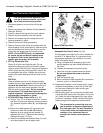
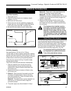
FP1193
Fig. 60 Install ceramic refractory panels.
Adjustable
Tab
Side
Panel
Floor
Refracotory
Panel
Lower Side
Supports
Back
Panel
Log Support
Burner Housing
Assy
Adjustable
Tab
Side
Panel
Floor
Refracotory
Panel
FP1194
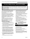
Fig. 61 Place the rear panel on rear support brackets.
Rear Refractory
Panel
Rear Panel
Support
Brackets
Rear Log
Support
Firebox Back