


8
Vermont Castings, Majestic Products DVRT36/39/43
10002428
The gas pipeline can be brought in through the side of
the fireplace as well as the bottom. Knockouts are
provided on the bottom behind the valve to allow for the
gas pipe installation and testing of any gas connection.
It is most convenient to bring the gas line in from the
rear right side of the valve as this allows fan installation
or removal without disconnecting the gas line.
The gas line connection can be made with properly
tinned 3/8” copper tubing, 3/8” rigid pipe or an ap-
proved flex connector. Since some municipalities have
additional local codes, it is always best to consult your
local authority and the CSA-B149.1 installation codes.
For USA installations consult the current National Fuel
Gas Code, ANSI Z223.1/NFPA 54.
Gas Line Installation
When purging the gas lines, the front
glass must be removed.
Always check for gas leaks with a mild
soap and water solution applied with a
brush no larger than 1” (25 mm). Never
apply soap and water solution with a
spray bottle. Do not use an open flame
for leak testing.
The fireplace valve must not be
subjected to any test pressures
exceeding 1/2 p.s.i. Isolate or disconnect
this or any other gas appliance control
from the gas line when pressure testing.
1. Thread the wiring through the electrical knockout
located on either side of the unit. Take care not to
cut the wire or insulation on metal edges. Ensure
the wire is secured and protected from possible
damage. Run one end to the gas control valve and
the other end to the conveniently located wall
switch.
2. Attach the wire to the ON/OFF switch and install the
switch into the receptacle box. Attach the cover
plate to the switch.
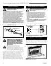
3. Connect the wire to the gas control valve. (Fig. 7)
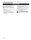
Remote ON/OFF Switch Installation
Do not wire the remote ON/OFF wall
switch for this gas appliance into a 120 V
power supply.
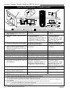
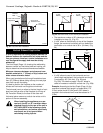
Alternate Switch Location
The remote switch can be installed on either side of the
access door. Mount the switch to the bracket provided
and screw the bracket to either side of the frame, using
the pre-punched holes. (Fig. 8)
TPTH
TH
TP
Remote
ON/OFF
Switch
W584-9
Fig. 7 Remote switch wiring diagram for R models.
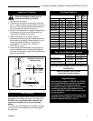
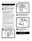
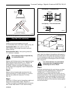
The gas control is equipped with a captured screw type
pressure test point; therefore, it is not necessary to
provide a 1/8” test point upstream of the control.
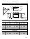
When using copper or flex connector use only ap-
proved fittings. Always provide a union when using
black iron pipe so that the gas line can be easily
disconnected for burner or fan servicing. (Fig. 6) See
the gas specifications for pressure details and ratings.
CFM104
Fig. 8 Alternate switch location.
FP297A
Fig. 6 Typical gas supply installation.
1/2” Gas Supply
1/2” NPT x 1/2” Flare
Shut-Off Valve
3/8” Flex Line
(From Valve)