


10004758
BREF Electric Fireplace
7
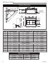
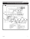
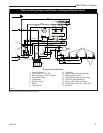
240 Volt Wall Switch Wiring Installation
A qualified electrician must perform any
electrical wiring of this appliance. For
Canadian installation, wiring must be done
in accordance with local codes, and/or
the current CSA C22.1 Canadian Electrical
Code. For U.S.A. installation, wiring must
be done in accordance with the National
Electrical Code ANSI/NFPA No. 70.
NOTE: For 240 Volt installations, use a double-pole,
single-throw, 20 Amp, 240V rated wall switch.
Wiring of the wall switch must be completed prior
to installing the unit.
Connect the wall-mounted switch to the fireplace by
running grounded 3-conductor wire (MIN. 14 AWG) to
the switch from the junction box on the side of the unit.
1. Locate the voltage selection switch under the logset
on the left front corner of the unit.
2. Move the switch from the 120 Volt to the 240 Volt
position.
3. Loosen the screws securing the junction box cover,
and remove the cover.
4. Remove knockouts in the box cover to use a cable
clamp.
5. Pull out three (3) wires: black, red, and white.
6. Connect one (1) wire (black) from the wall switch to
the L1 (black) wire on the unit, and the other wire
from the wall switch to the L1 (black) wire on the
power supply.
7. Connect one (1) of the wires from the wall switch to
the L2 (red) wire on the unit, and the other wire from
the wall switch to the L2 (red) wire on the power sup-
ply.
8. Connect the white wire from the unit to the neutral
(white) wire on the power supply.
9. Connect the ground wire from the wall switch to the
wire grouping from the power supply and ground
stud in the junction box.
10. Ensure all connections are tight. Insert all wiring
inside the junction box and secure the cover.
7. Connect the white wire from the unit to the neutral
(white) wire on the power supply.
8. Connect the ground wire from the wall switch to the
wire grouping from the power supply and the ground
stud in the junction box.
9. Make sure the red wire (L2) in the junction box has a
closed end splice or a wire nut properly applied.
10.Ensure all connections are tight. Insert all wiring
inside the junction box and secure the cover.
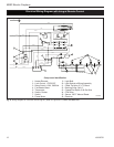
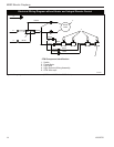
120/240 Volt Wall-Mounted
Thermostat Wiring
Before attempting maintenance or ser-
vice—to reduce risk of fire, electrical
shock and personal injury—disconnect all
power to the fireplace at the main service
panel.
NOTE: Wiring of the wall thermostat must be com
-
pleted prior to the installation of the unit.
Use a single pole thermostat rated for 120/240 Volt
operation.
When installing the wall thermostat, make sure to
turn the heater control inside fireplace all the way
clockwise to the highest set point temperature.
Connect the wall-mounted thermostat to the fireplace
by running a grounded 2-conductor wire (min. 14 AWG)
to the thermostat from the junction box on the side of
the unit.
1. Loosen the screws securing the junction box cover
and remove the cover.
2. Remove knockouts in the box cover to use a cable
clamp.
3. Pull out the two (2) brown wires with the closed end
splice at the end.
4. Cut off the closed end splice, separate the two wires,
and strip approximately 5/8" (15mm).
5. Connect one (1) wire from the thermostat to one (1)
of the brown wires; connect the other wire from the
thermostat to the other brown wire.
6. Connect the ground wire from the wall thermostat to
the power supply wire group and the ground stud in
the junction box.
7. Ensure all connections are tight. Insert all wiring into
the junction box and secure the cover.
Installation Cautions
Make sure the power is turned OFF before
proceeding.
If repairing or replacing any electrical com-
ponent or wiring, the original wire routing,
color coding and securing locations must
be followed.
Any electrical repairs or rewiring of this
unit should be carried out by a licensed
electrician in accordance with national and
local codes.