


10004758
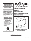
BREF Electric Fireplace
6
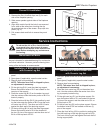
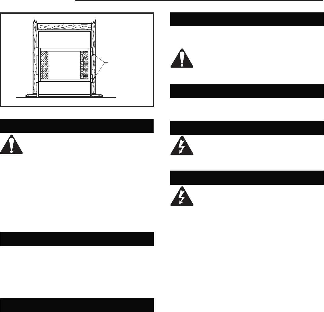
Finishing
CAUTION: All joints between the finished
wall and the appliance surround (top and
sides) may be sealed only with noncom-
bustible material. Only noncombustible
material can be applied as facing to
the appliance surround (the black painted
face).
When finishing the appliance, never obstruct or
modify the air inlet/outlet grilles in any manner.
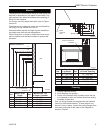
NOTE: Finish the wall with the material of your
choice. Refer to Figures 2a and 2b for specific
clearances when installing a combustible mantel or
other combustible projection.
Locating your Electric Fireplace
Your new fireplace may be installed into an existing
masonry or zero-clearance fireplace. It may also be in
-
stalled using a prefabricated cabinet available from your
dealer, or be built into a wall.
When choosing a location for your new fireplace, en
-
sure that the general instructions are followed. Also, for
best effect, install the fireplace out of direct sunlight.
Clearance to Combustibles
Sides ......................................................... 0" (0 mm)
Floor .......................................................... 0" (0 mm)
Top ........................................................... 0" (0 mm)
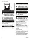
FP549
9/29/97
BR/BC
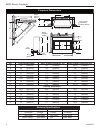
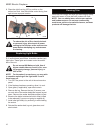
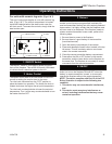
Nail
side-nailing
flange
Fig. 3 Adjustable drywall strip (nailing flange).
FP549
Hearth
A hearth is not mandatory; however, for aesthetic pur-
poses, we recommend use of a noncombustible hearth
that does not obstruct the air openings.
Cold Climate Installation: To conform to
applicable insulation codes, it is manda-
tory the outer walls be insulated when
installing this unit against a non-insulated
exterior wall or chase.
Cabinet Installations
Cabinets are available from your dealer which allow
fast, convenient installation of your fireplace against
existing walls.
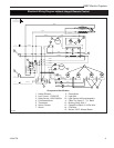
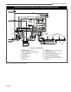
Main Power Wall Switch Wiring
To reduce the risk of fire, electrical shock,
and personal injury, before attempting
maintenance or service, disconnect all
power to the fireplace
at the main service panel.
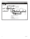
120 Volt Wall Switch Wiring Installation
A qualified electrician must perform any
electrical wiring of this appliance. For Ca-
nadian installations, wiring must be done
in accordance with local codes, and/or
the current CSA C22.1 Canadian Electrical
Code. For U.S.A. installations, wiring must
be done in accordance with the National
Electrical Code ANSI/ NFPA No. 70.
NOTE: For 120 Volt installations, use a
single-pole, single-throw, 20 Amp-rated wall switch.
(NH models do not require the 20 Amp switch. A
regular 15 Amp wall switch may be used.)
Wiring of the wall switch must be completed prior
to installing the unit.
Connect the wall-mounted switch to the fireplace by
running grounded 2-conductor wire (Min. 14 AWG) to
the switch from the junction box on the side of the unit.
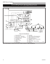
1. Locate the voltage selection switch under the logset
on the left front corner of the unit. (Not applicable to
NH models)
2. Ensure the switch is in the 120 Volt position. (Not
applicable to NH models.)
3. Loosen the screws securing the junction box cover,
and remove the cover.
4. Remove knockouts in the box cover to use a cable
clamp.
5. Pull out two (2) wires: black and white.
6. Connect the hot wire (black) from the wall switch to
the L1 (black) wire on the unit, and the other wire
from the wall switch to the L1 (black) wire on the
power supply.