


10004758
BREF Electric Fireplace
5
J
F
G
H
I
CFM164a
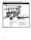
Mantel Leg Chart
06/22/01 sta
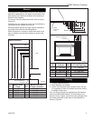
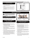
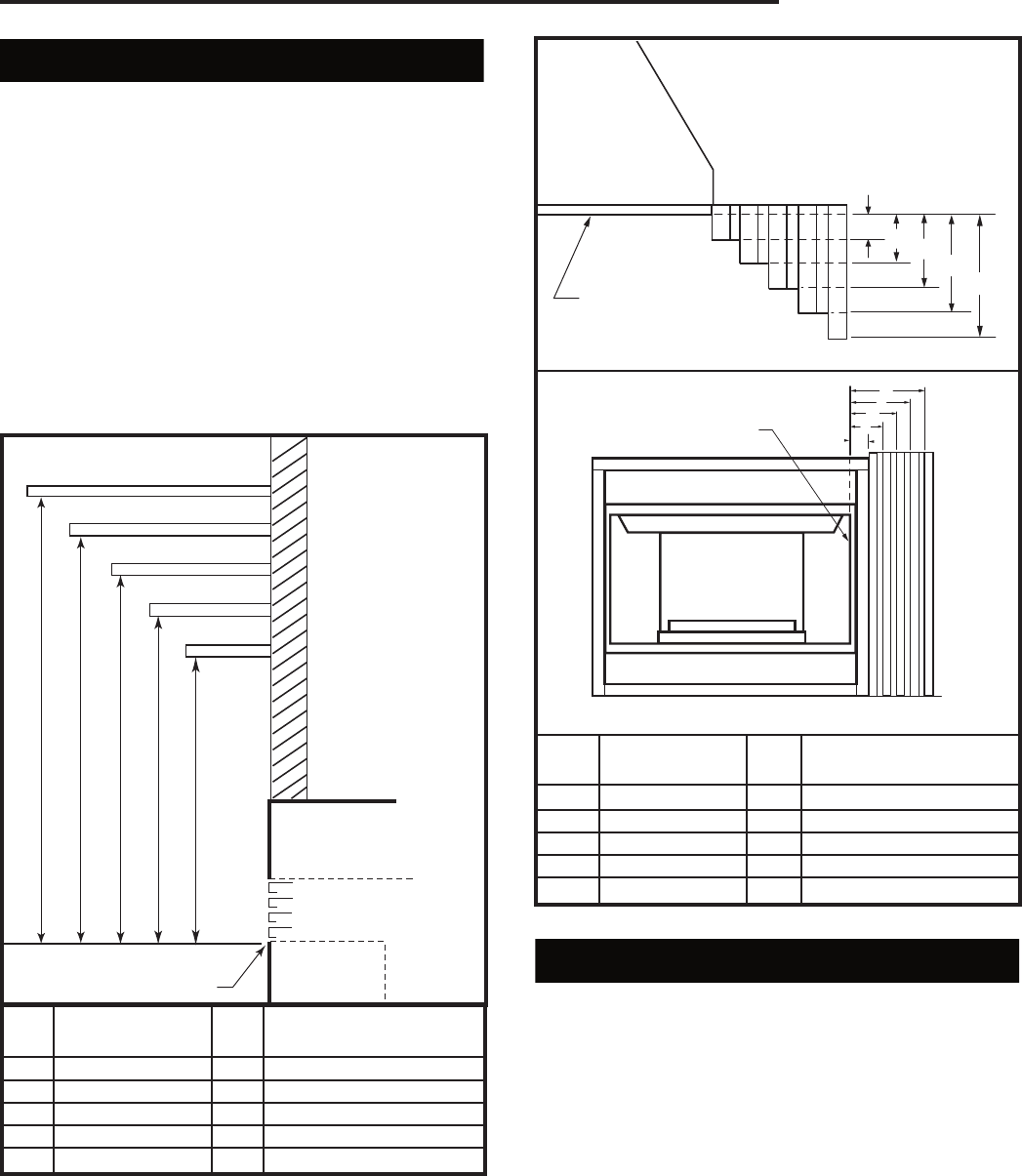
Mantels
The height that a combustible mantel is fitted above the
fireplace is dependent on the depth of the mantel. This
also applies to the distance between the mantel leg (if
fitted) and the fireplace.
For correct mounting height and width, refer to Figure
2a and 2b.
The distances and reference points are not affected by
the fitting of a bay window front trim kit.
Noncombustible mantels and legs may be installed at
any height and width around the appliance.
When using paint or lacquer to finish the mantel, such
paint or lacquer must be heat-resistant to prevent dis-
coloration.
Black
Surround
Face
CFM164a
CFM170
DV Builder Front
View
O
N
M
L
K
Side of Combustion
Chamber
CFM170
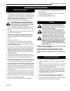
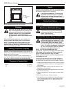
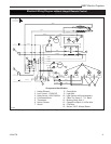
Fig. 2b Combustible mantel leg minimum installation.
Mantel Mantel Leg from Side
Ref.
Leg Depth
Ref.
of Comb. Opening
F 14" (356 mm) K 14" (356 mm)
G 12" (305 mm) L 12" (305 mm)
H 10" (254 mm) M 10" (254 mm)
I 8" (203 mm) N 8" (203 mm)
J 1
¹⁄₂" (38 mm) O 1¹⁄₂" (38 mm)
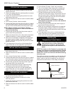
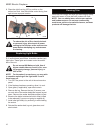
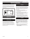
Framing
1. Choose fireplace location.
2. Place fireplace into position.
3. Frame in the fireplace with a header across the top.
It is important to allow for finished face when setting
the depth of the frame.
Four (4) nailing flanges are supplied with the fireplace
(found on the fireplace hearth). To level the box and
secure it firmly in place, remove the nailing flanges from
the hearth and install at the sides of the fireplace as
shown in Figure 3.
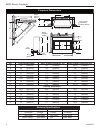
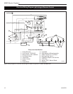
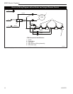
Mantel Shelf Mantel from Top
Ref.
Depth
Ref.
of Comb. Chamber
V 14" (356 mm) A 25" (635 mm)
W 12" (305 mm) B 23" (584 mm)
X 10" (254 mm) C 21" (533 mm)
Y 8" (203 mm) D 19" (483 mm)
Z 1
¹⁄₂" (38 mm) E 15" (381 mm)
A B C
D
E
V
W
X
Y
Z
CFM146c
Electric Mantel
Chart
1/22/04 djt
Wall
Top of Combustion
Chamber
CFM146b
Fig. 2a Combustible mantel minimum installation.
Mantel Clearances
Mantel Leg